A friend of mine asked if I could help convert a vintage, bakelite, rotary dial phone into a table lamp. Obviously I couldn’t say no to such an absurd challenge, but found her expectation for the project to be somewhat unremarkable, all she wanted was a white LED bulb and an on/off switch… this simply would not do.
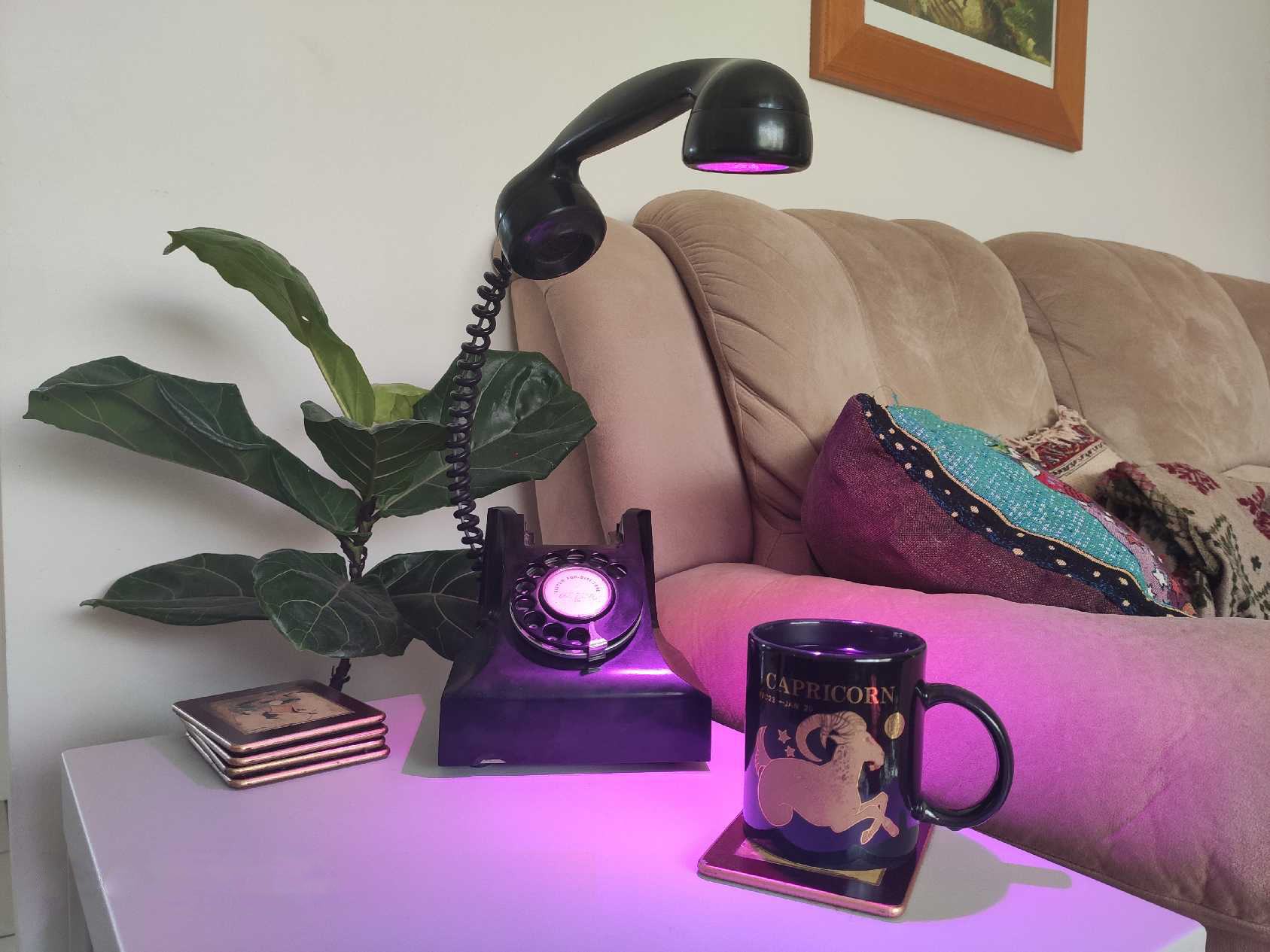
I received the phone already stripped with a hole cut in the receiver, due to this pesky covid thing, getting parts has been rather difficult, so the thing would have to be built from scraps in my parts bin and things that RS had in stock.
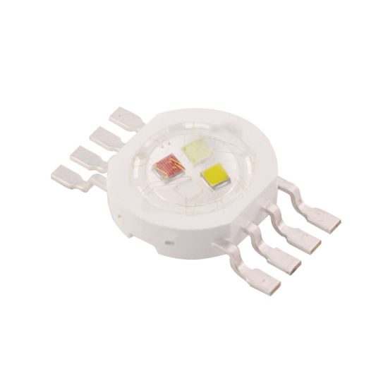
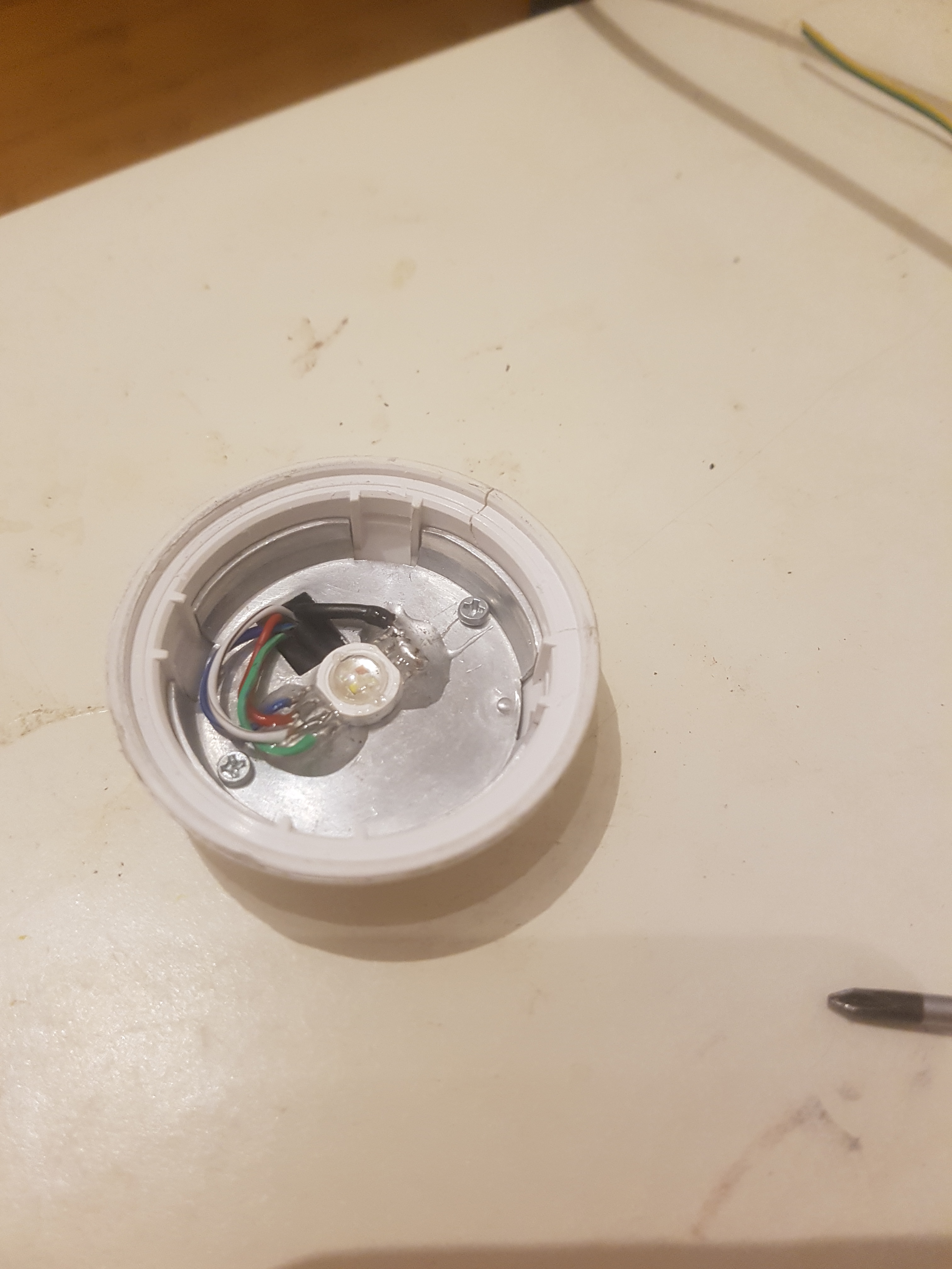
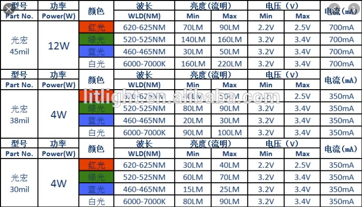
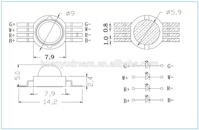
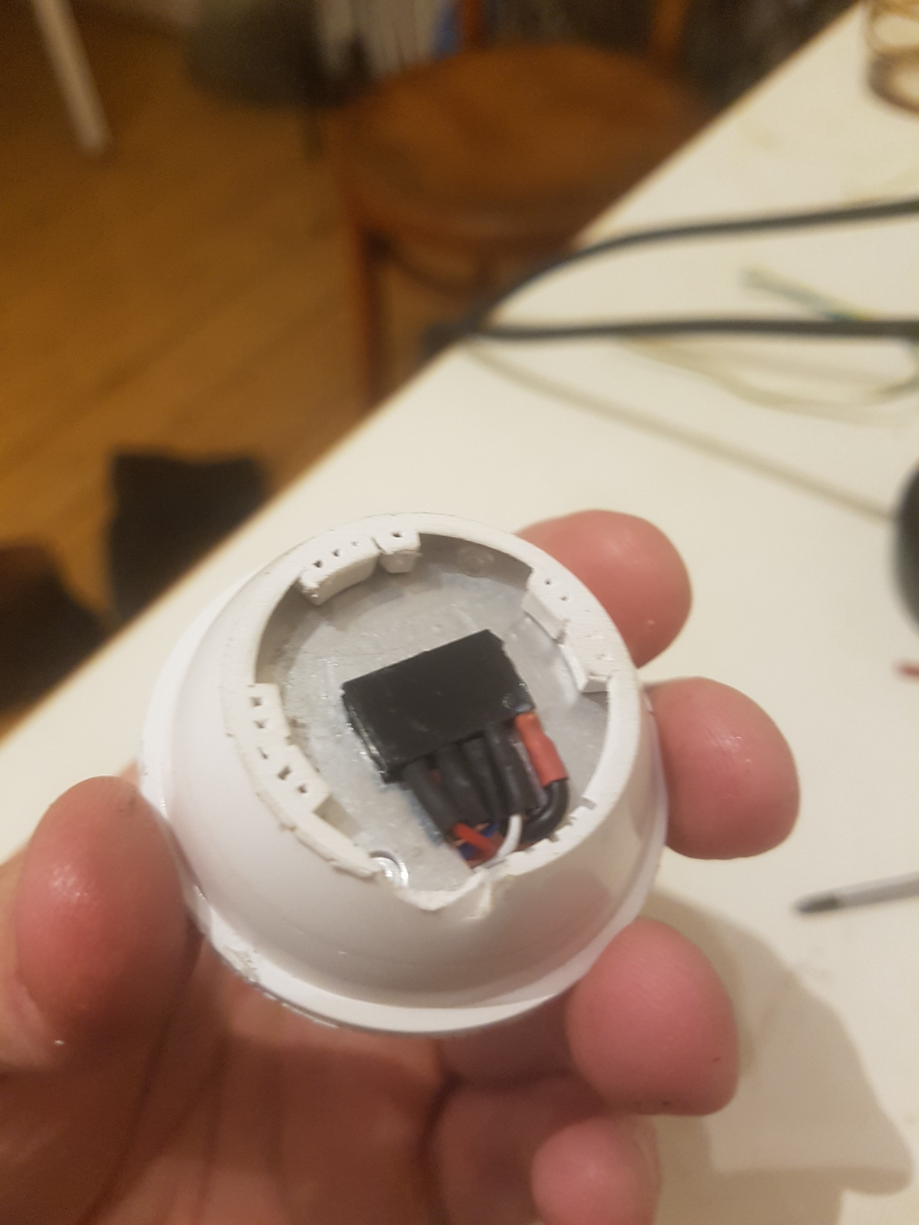
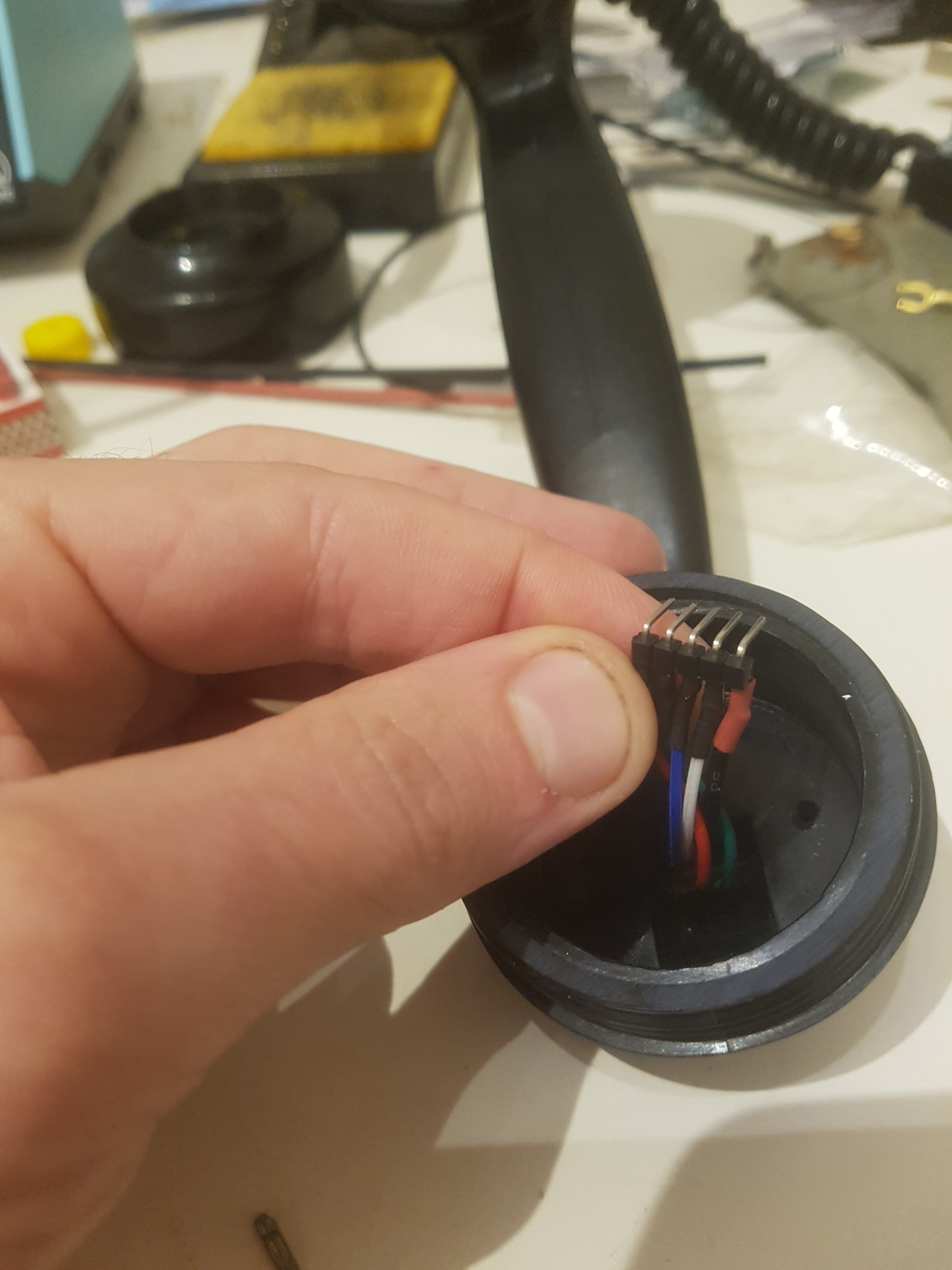
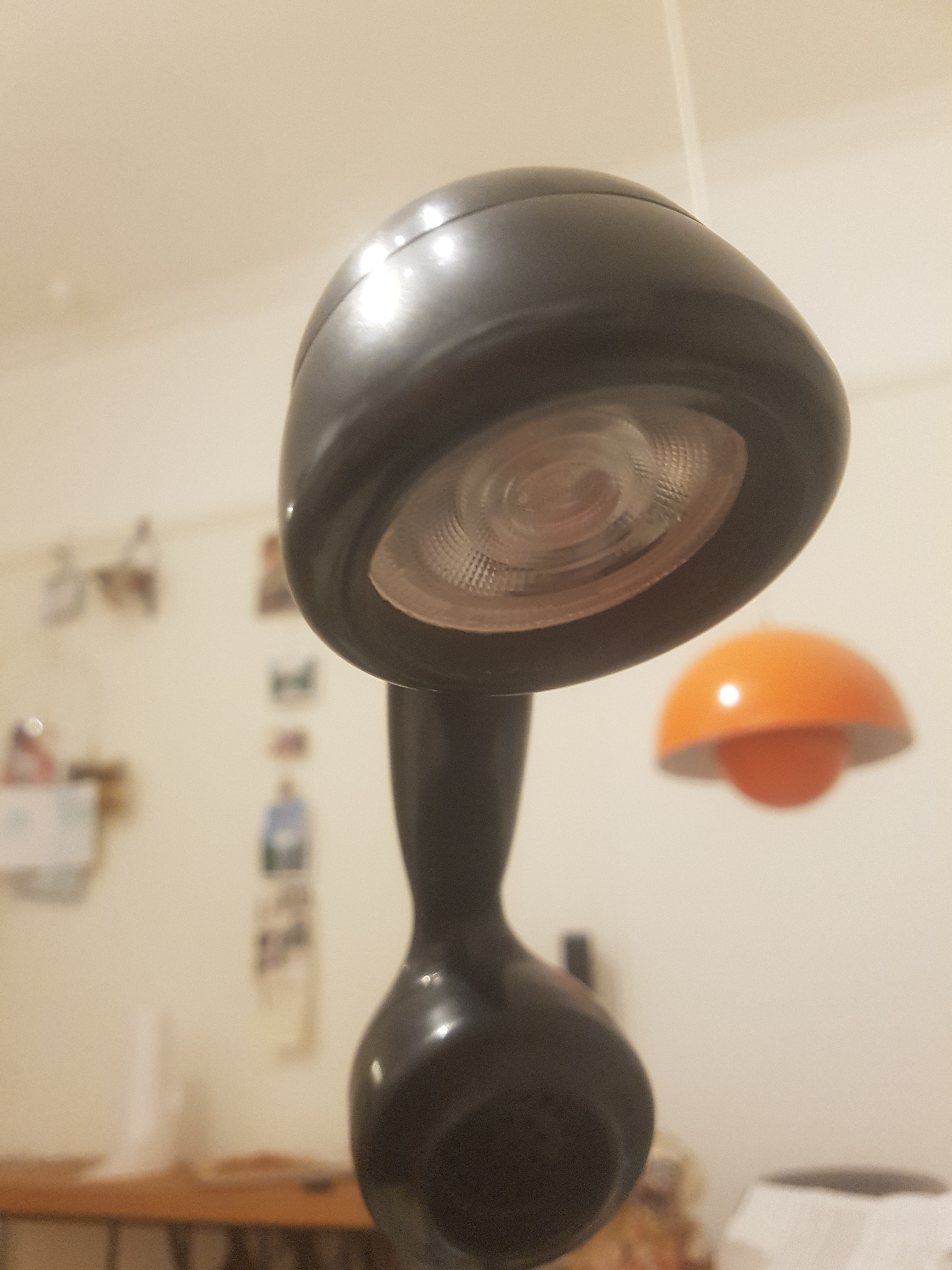
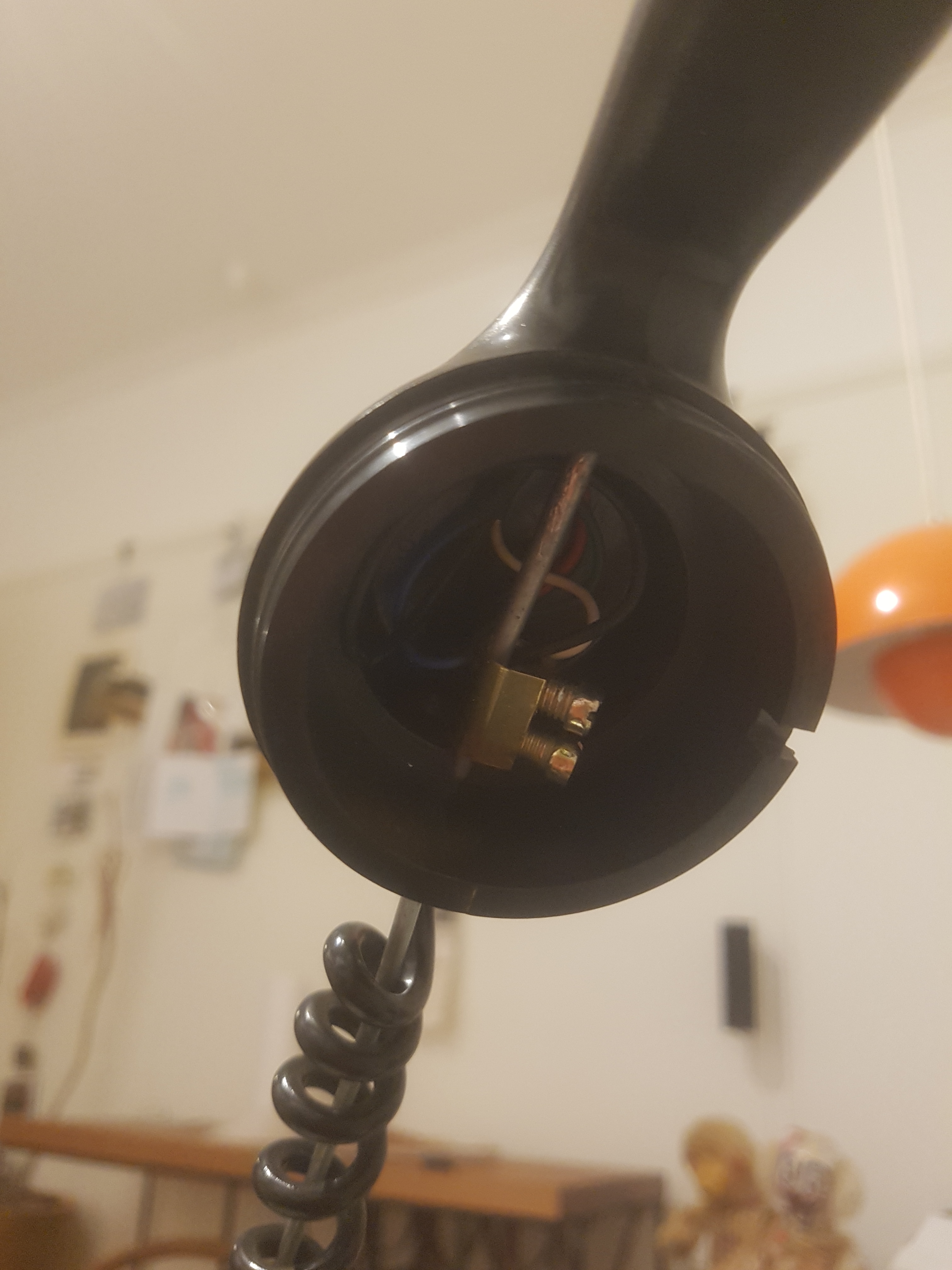
I ordered a 4 watt RGBW LED which I quickly went about installing. The lamp assembly would be made from a 12 volt downlight which I machined the back off in the late, removing the LED board and power supply. I then soldered the 4 cathodes to a header strip with their respectively colour coded wires, and bridged the anode to a common terminal. This was then epoxied onto the aluminium heat sink from the downlight, the lens popped back on, and the assembly screwed securely into place with the earpiece cover. I must note that 4 watts is the collective output, and that each of the four diodes in this package are only 1 watt each. If you wanted to make a blinding bedside lamp you could use a 12 watt version… but that would literally be insane.
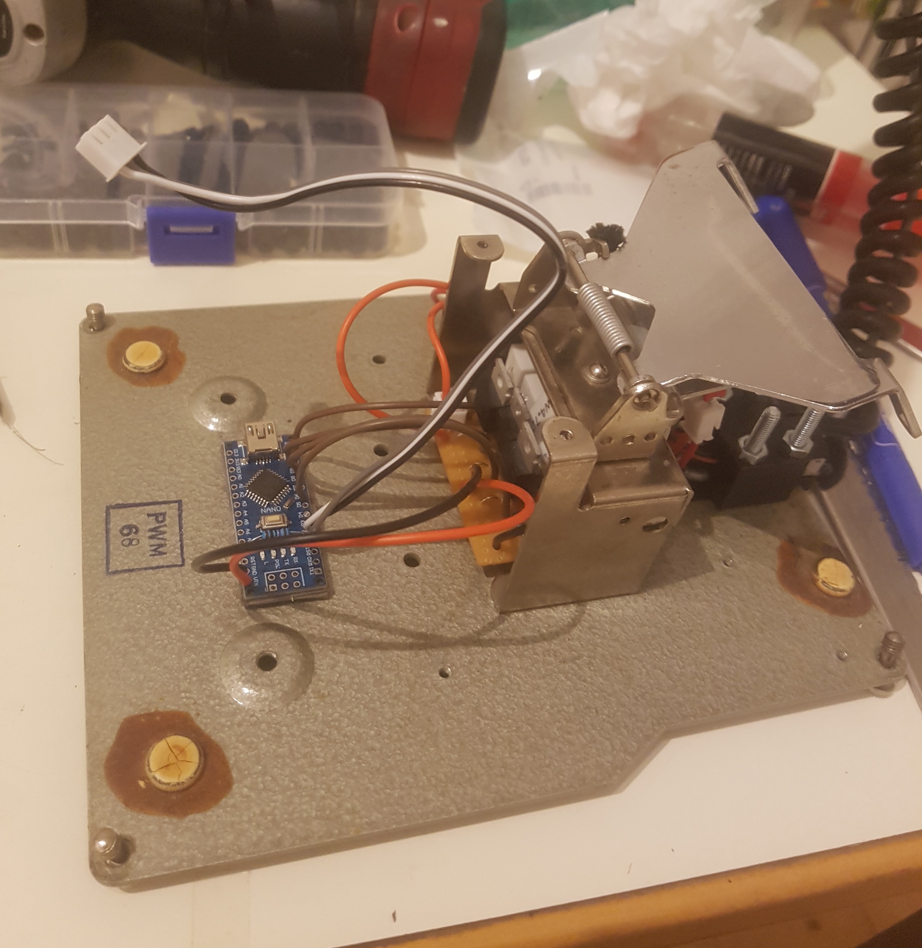
Inside the phone I built a very simple circuit using four 30n06le N-channel mosfets driven from an Arduino Nano and the appropriate current limiting resistor, remembering that the red LED requires a lower voltage and thus larger resistor. The resistors were a hodgepodge of ceramic and 3 watt metal film types, with some parallel banking required to get to the right values, but I was working with scrap and no one will ever see it or judge me for it… I hope.
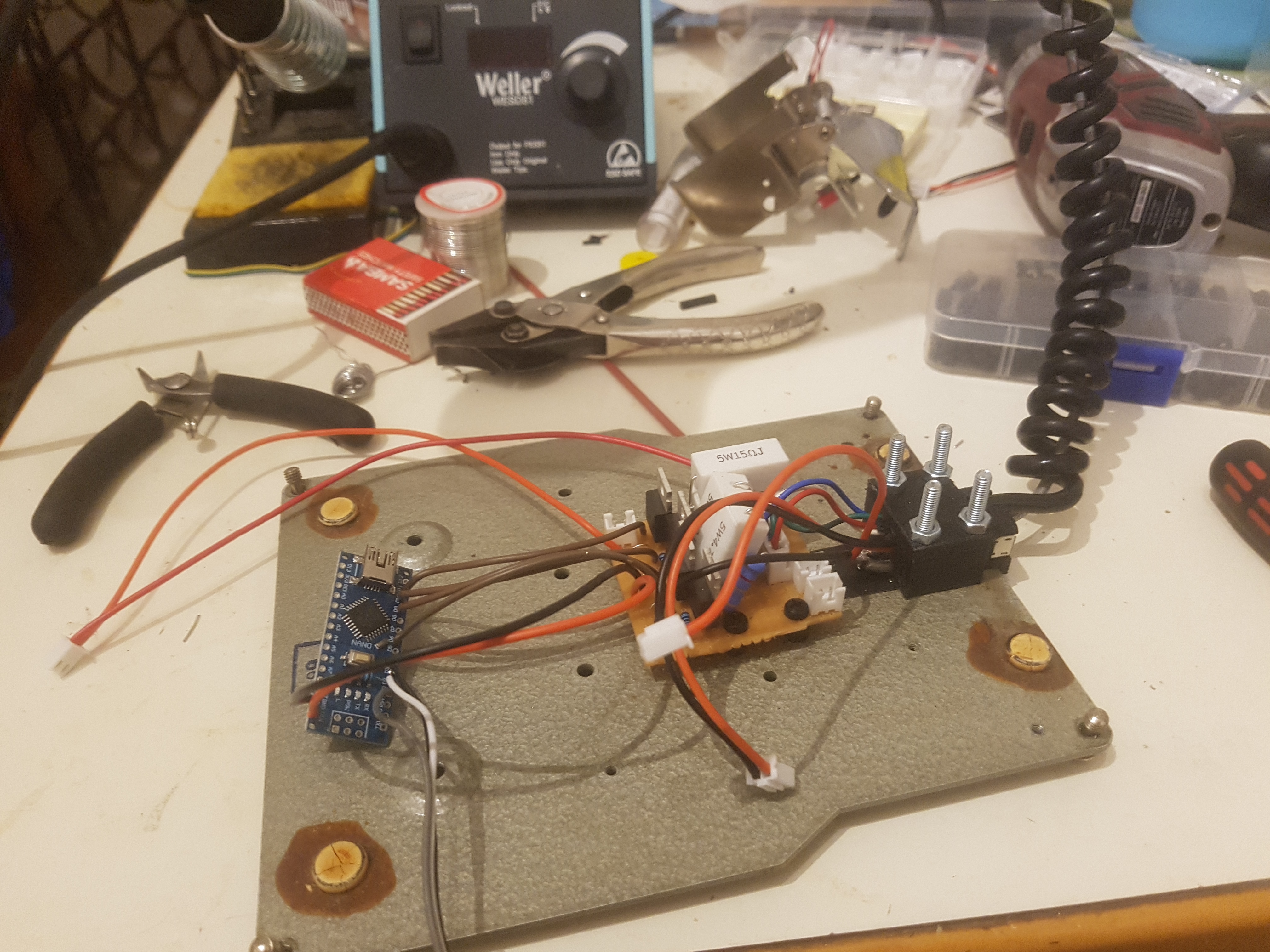
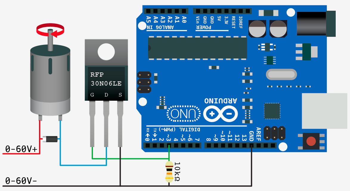
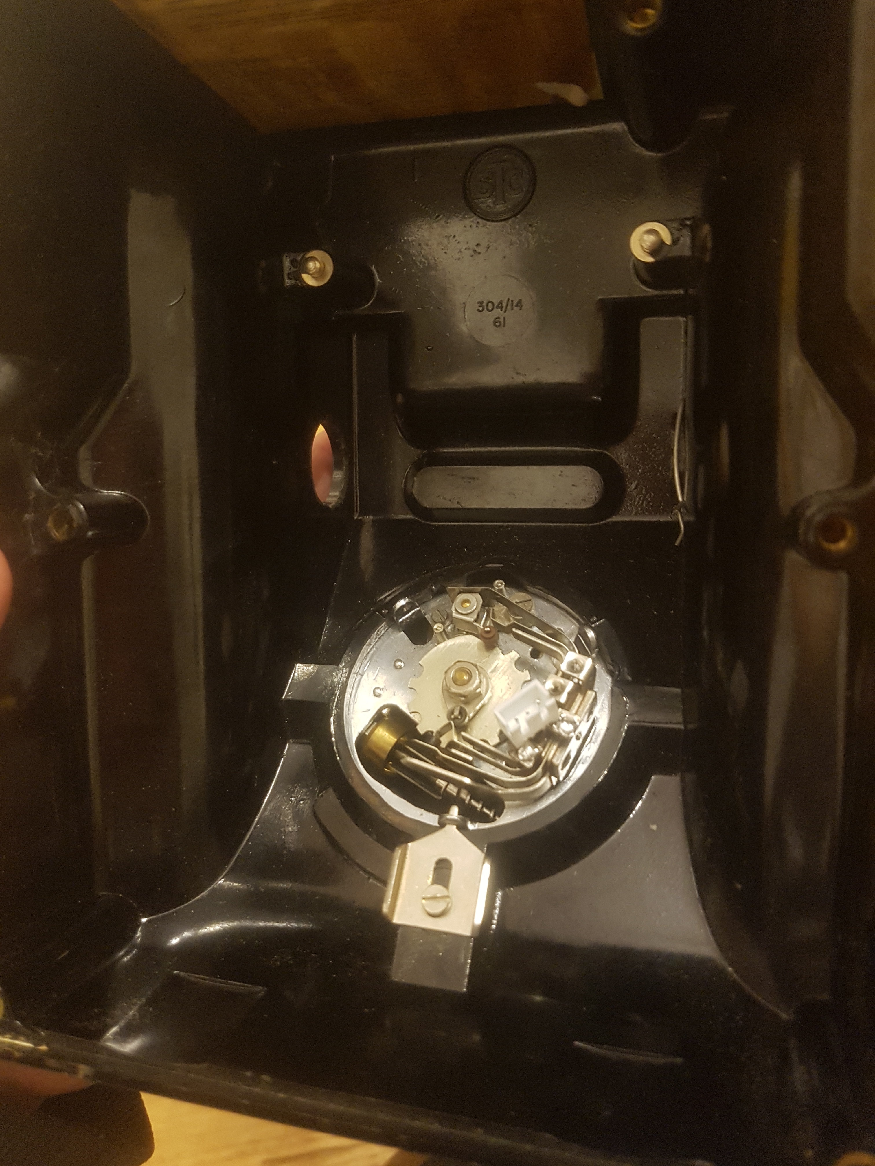
The Arduino is connected to the rotary dial mechanism via three wires, a ground, a data wire with a 10k pull-up resistor, and a second floating data wire. This arrangement worked for my rotary dial mechanism but might have to be altered for yours. Essentially the switch configuration in mine is such that before a number is dialed the non-pulled up data wire is connected to the pulled-up data wire, so they are effectively both in a high state. However once dialing starts, the non pulled up wire is switched to ground for the duration of the dialing, while the pulled-up wire is shorted to ground on every pulse of the dial. Thus by reading the non pulled-up data wire you can tell if the dial is being activated or not, and then command the Arduino to start counting pulses from the pulled-up data wire. I realize that was a terrible explanation and urge you to have a look on the googles for some actual examples of this with test code, there are heaps around.
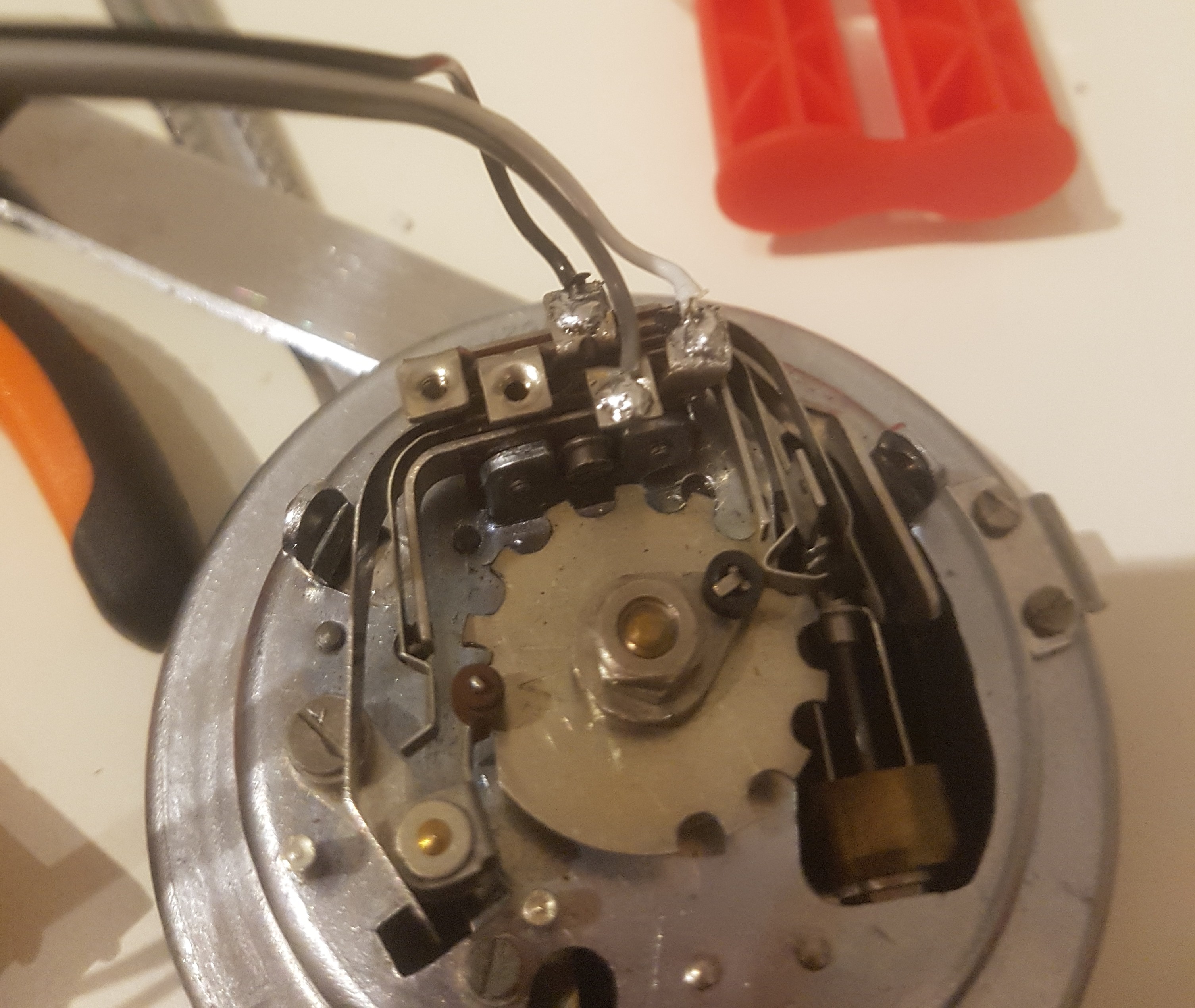
You can steal some example code from other people who have made projects with rotary dial mechanisms and tweak it to your setup, I think coming up with the code for this thing probably took the least amount of time.
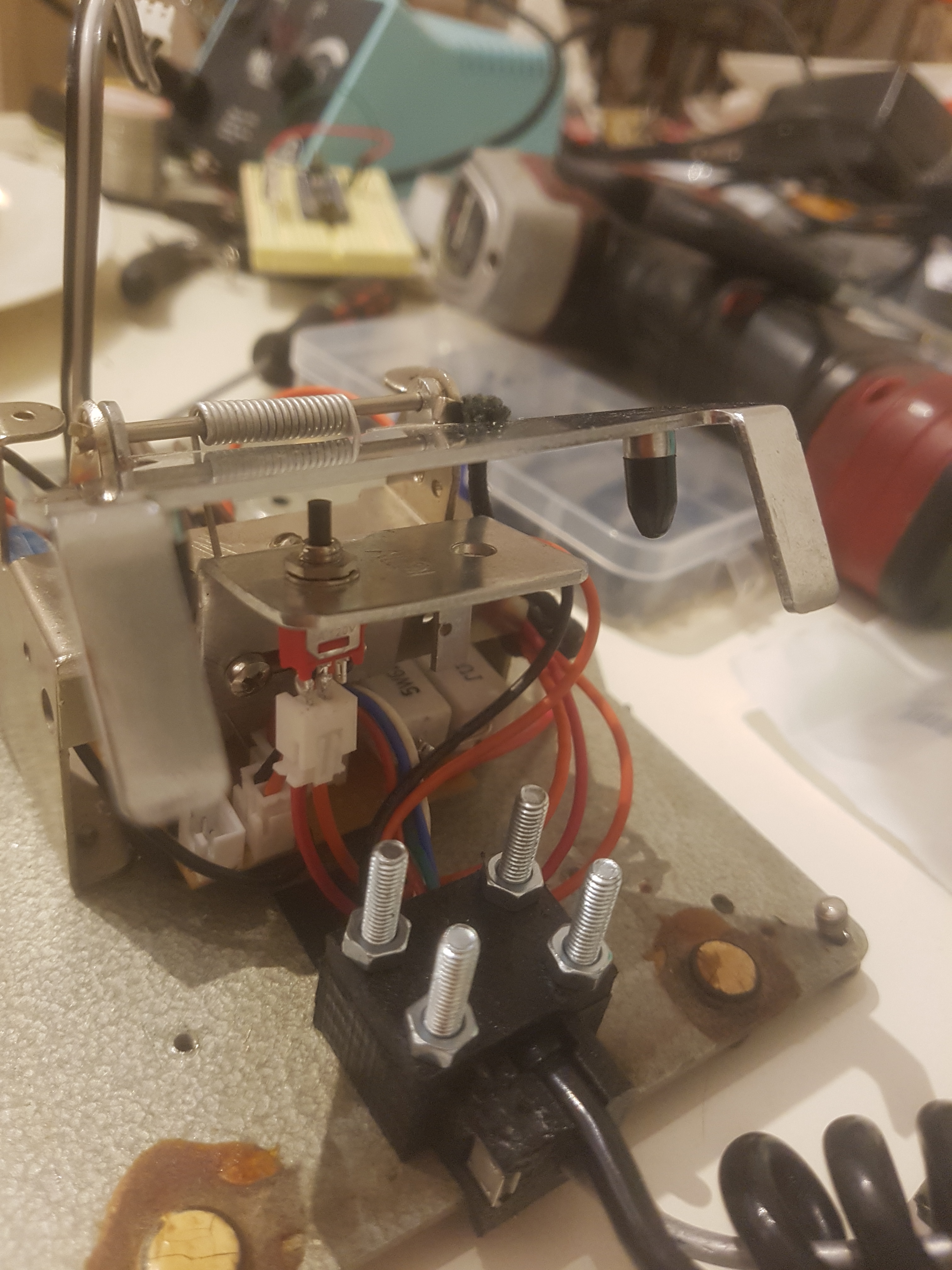
For holding the receiver I opted for some heavy gauge fencing wire that I had a coil of in the shed. I chose this as it’s easy to overlook hiding inside the middle of the original coiled wire, and is also really malleable, so allows the lamp to be moved and bent into lots of positions. I designed and 3D printed a mount for the fencing wire which bolted to the base plate of the phone and also held the cable, and micro USB jack to power the whole thing. This was secured with 4 slightly over-sized bolts and made for a very tough arrangement. The plastic mounting block also served to insulate and isolate the fencing wire from the metal phone base, as the fencing wire is carrying constant the positive voltage to the LED common anode.
Inside the phone I mounted a switch to the original receiver switch bracket and added an insane amount of header sockets to everything to make assembly less of a hellish nightmare. The switch turns the power off and on to the positive rail of the Arduino and LED supply.
I also ended up adding a header socket to the rotary dial mechanism, and for some reason gave up on life and secured the Arduino to the base plate of the phone using double sided foam tape.
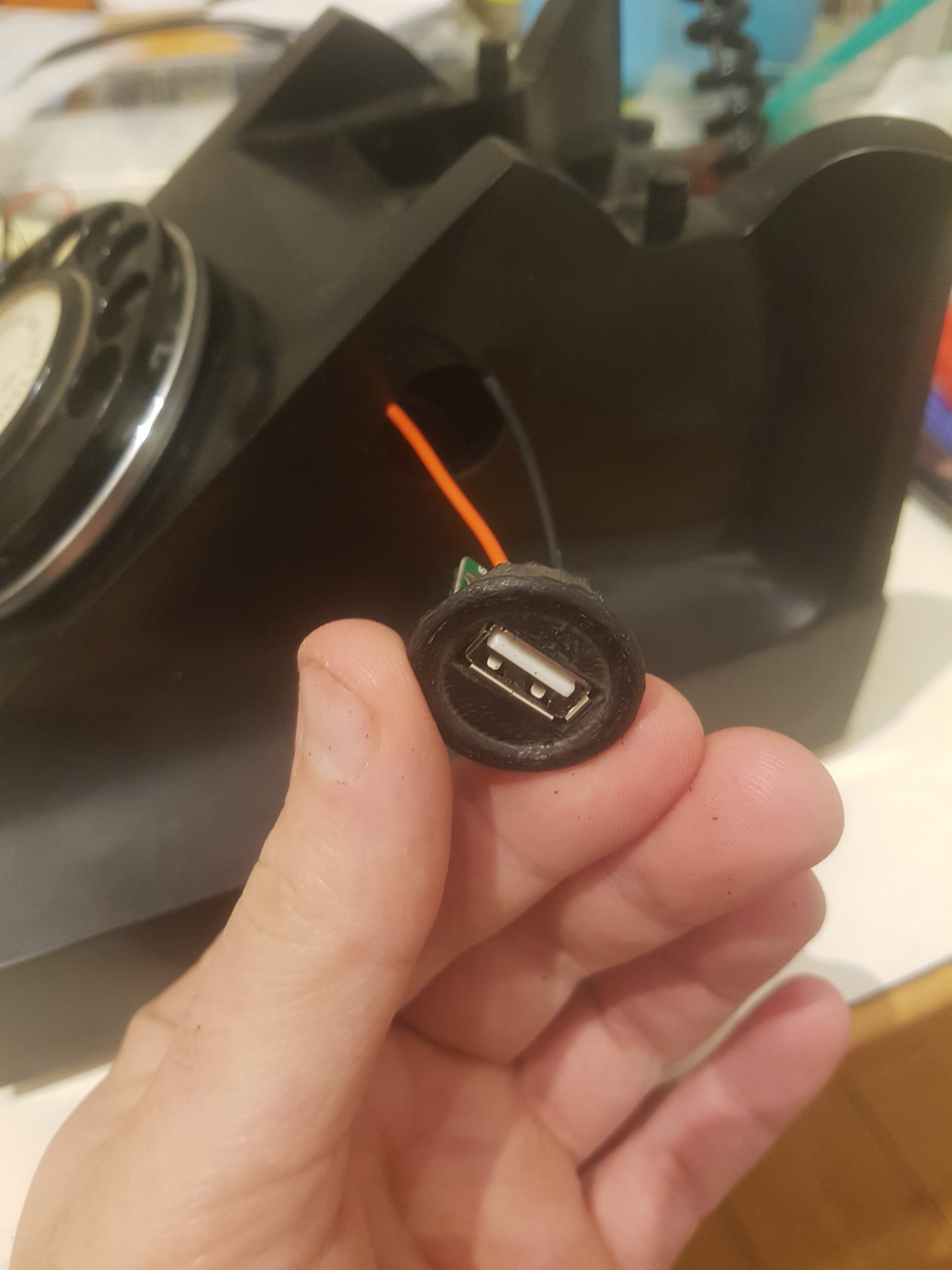
I’d noticed during the construction of this project that one of the cover plates on the side of the phone body had gone missing probably many years ago. I decided that trying to duplicate the original one would be kind of lame, as I could make an even better one with a USB socket for phone charging… this port is constantly connected to the supply power regardless of if the lamp is on or not.
The last step was choosing a nice range of colours, one for each number on the dial. Having the white LED makes it easy to desaturate colours, but also means that you don’t get any rainbow effect from trying to make pure white from blending red, green, and blue. It probably wasn’t necessary, and I could have gotten away with just an RGB diode, but that wouldn’t have been as fun. I just used the PWM function on the digital pins on the Arduino and assigned values manually for each channel, it was actually surprisingly quick and intuitive to do, especially if you grew up using MS paint. The mosfets and resistors that I used were stupidly over specified for the job, so nothing even gets warm after hours of bench testing.
I’ll post the code up here too, but I must warn you that it’s very basic, and you’ll probably judge me pretty harshly for it.