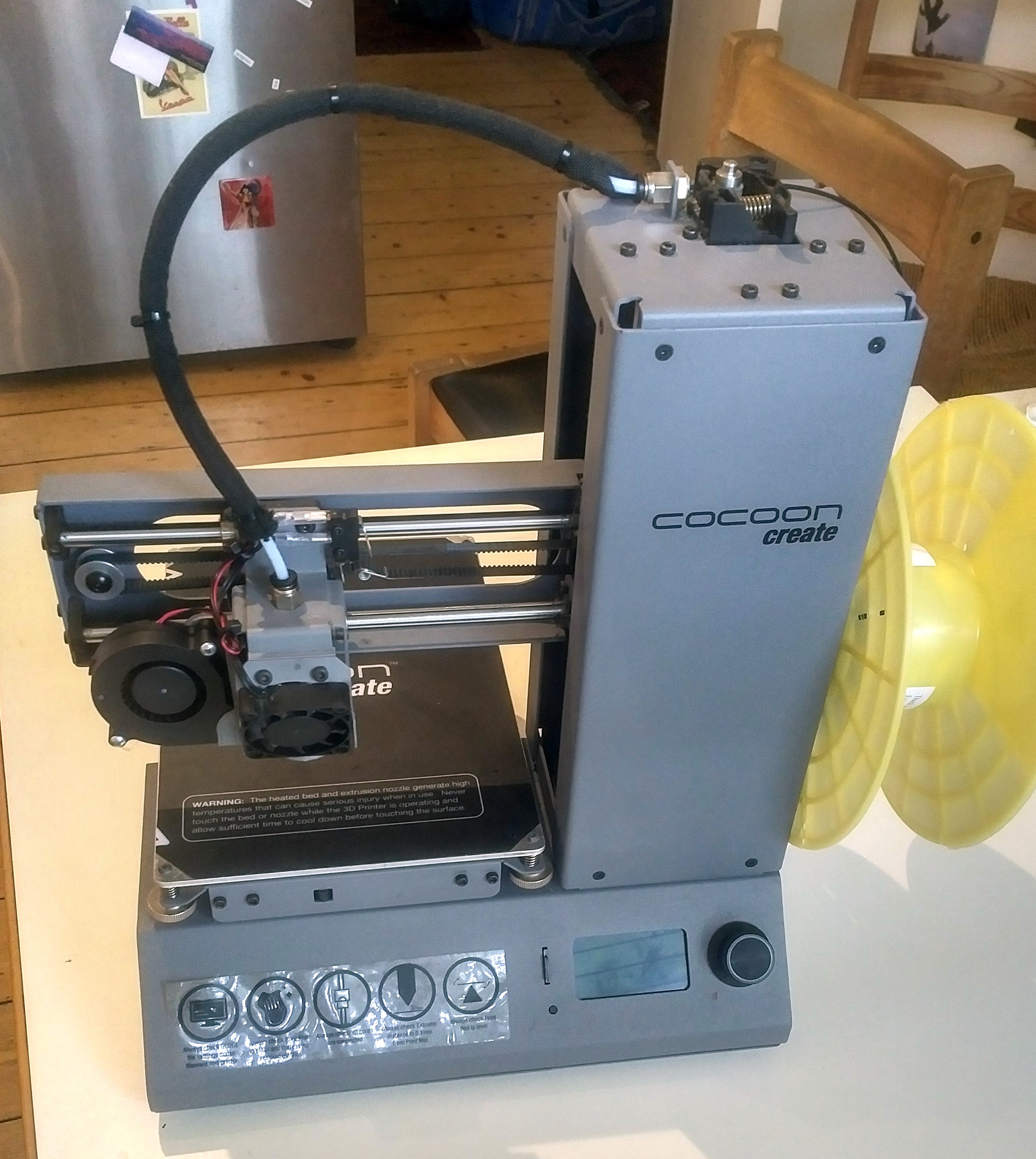
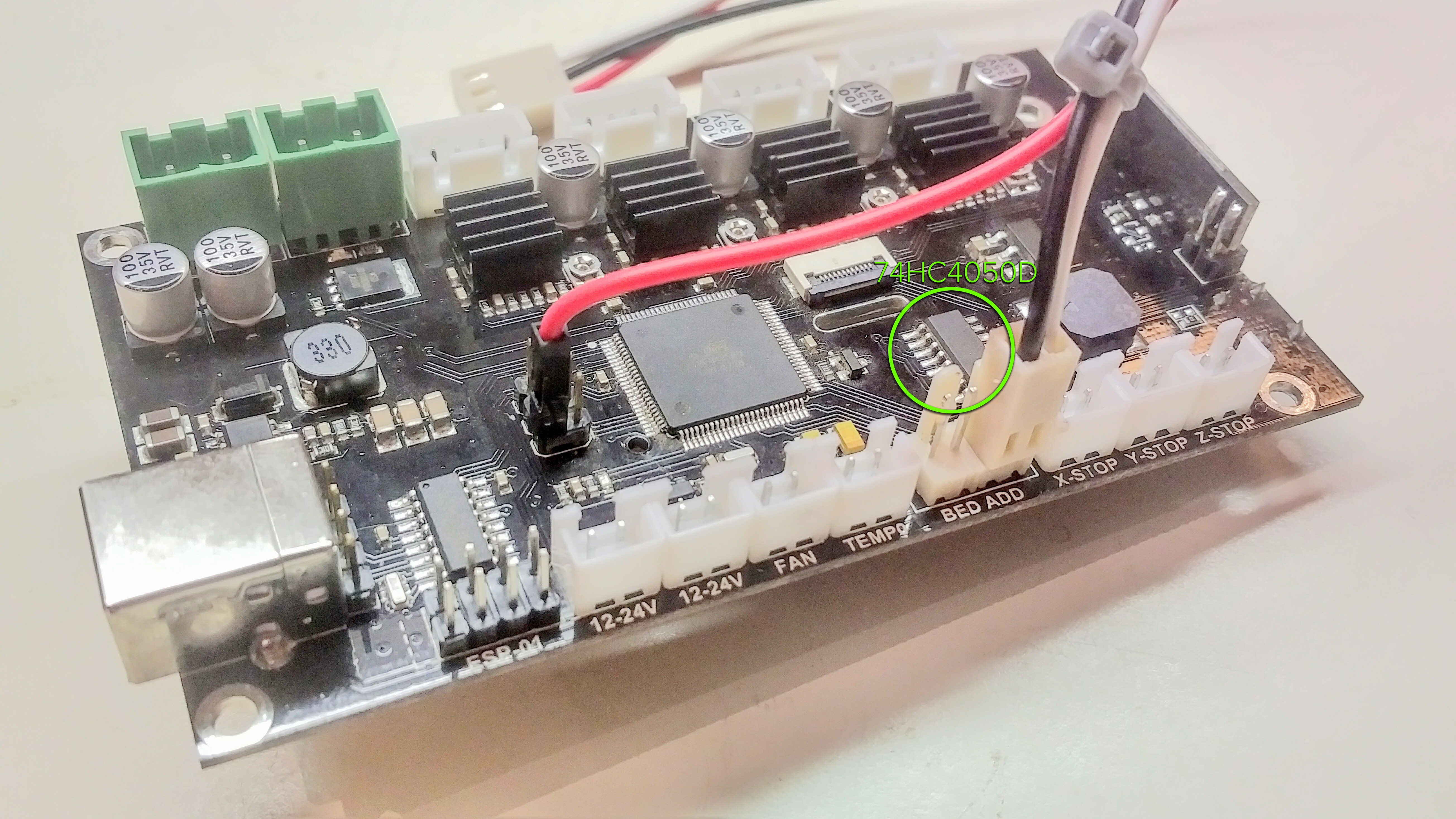
I bought a Wanhao Duplicator i3 Mini from ebay for about $40 broken, figuring that it would be an easy repair. The screen was apparently not working, so i figured that it was probably a faulty LCD panel. After replacing the panel I soon discovered that the problem was somewhere else, and with a bit of probing around with the multi-meter I soon found the culprit which was the 74HC4050D hex level shifter… which essentially just translates the logic state levels between 3.3 volt and 5 volts for the Arduino. This is used not only for driving the LCD screen but also communicating with the SD card, so if you have one of these printers and the SD card is not functioning, this is your culprit.
After getting the printer running I soon discovered how annoying it was to not have a heated bed with constant bed adhesion failures… so it was time to add a heater to the bed! After looking around online I soon found that a few people had used the “Bed Add” pins from the motherboard to add a thermocouple and drive a MOSFET off the 5 volt PWM output from the Arduino. This however required a larger external power supply to drive the heated bed with, and a MOSFET that enjoys 5 volt PWM signals, which all seemed like lots of work, and defeated the purpose of a small form factor printer.
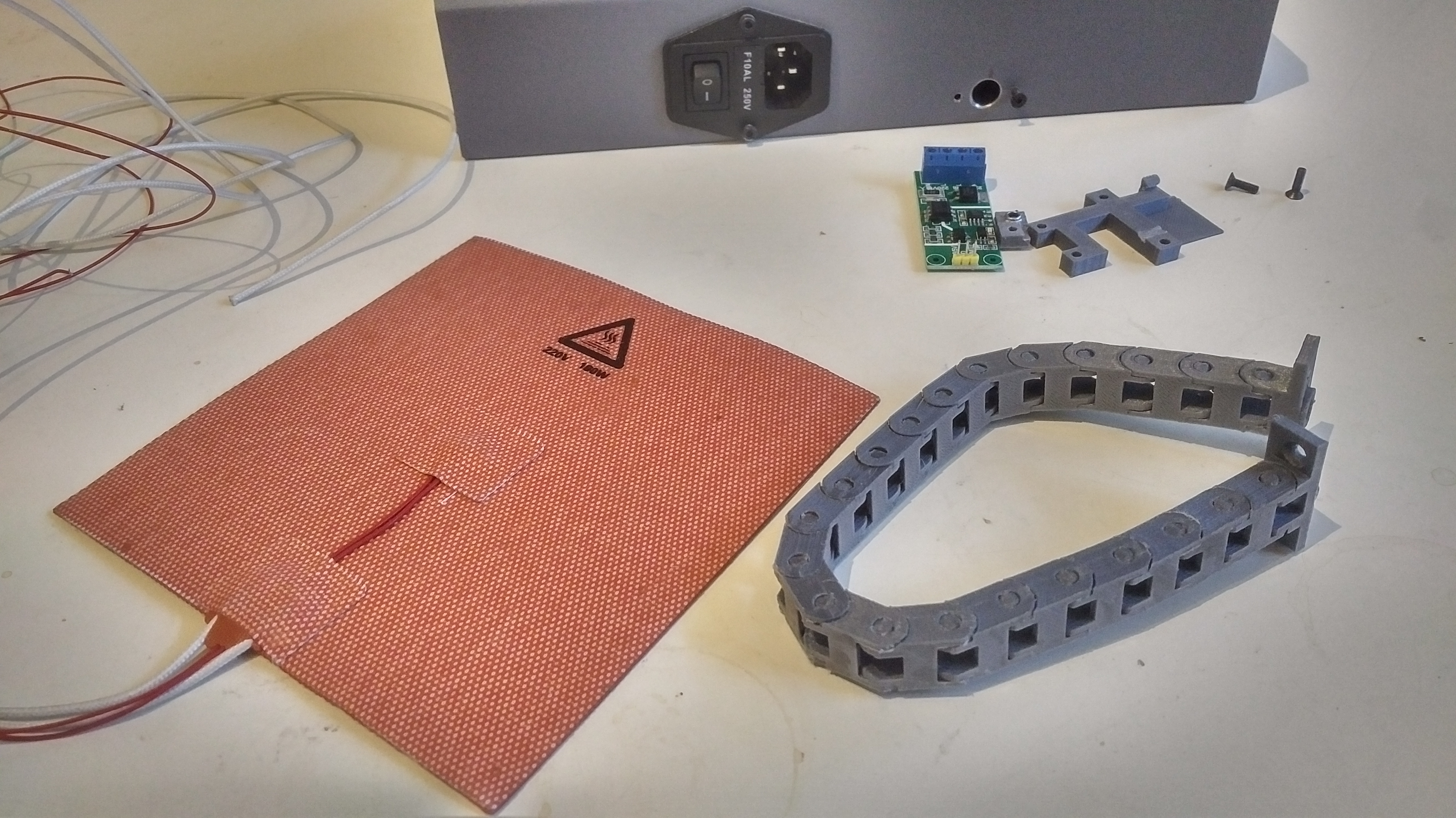
I instead opted for a silicone 220 volt AC heated mat driven from a TRIAC module that accepts both 5 volt and 3.3 volt PWM logic levels. I can sense that some people will be terrified of AC mains power, and in that case, go for the DC heated bed with the external power supply.
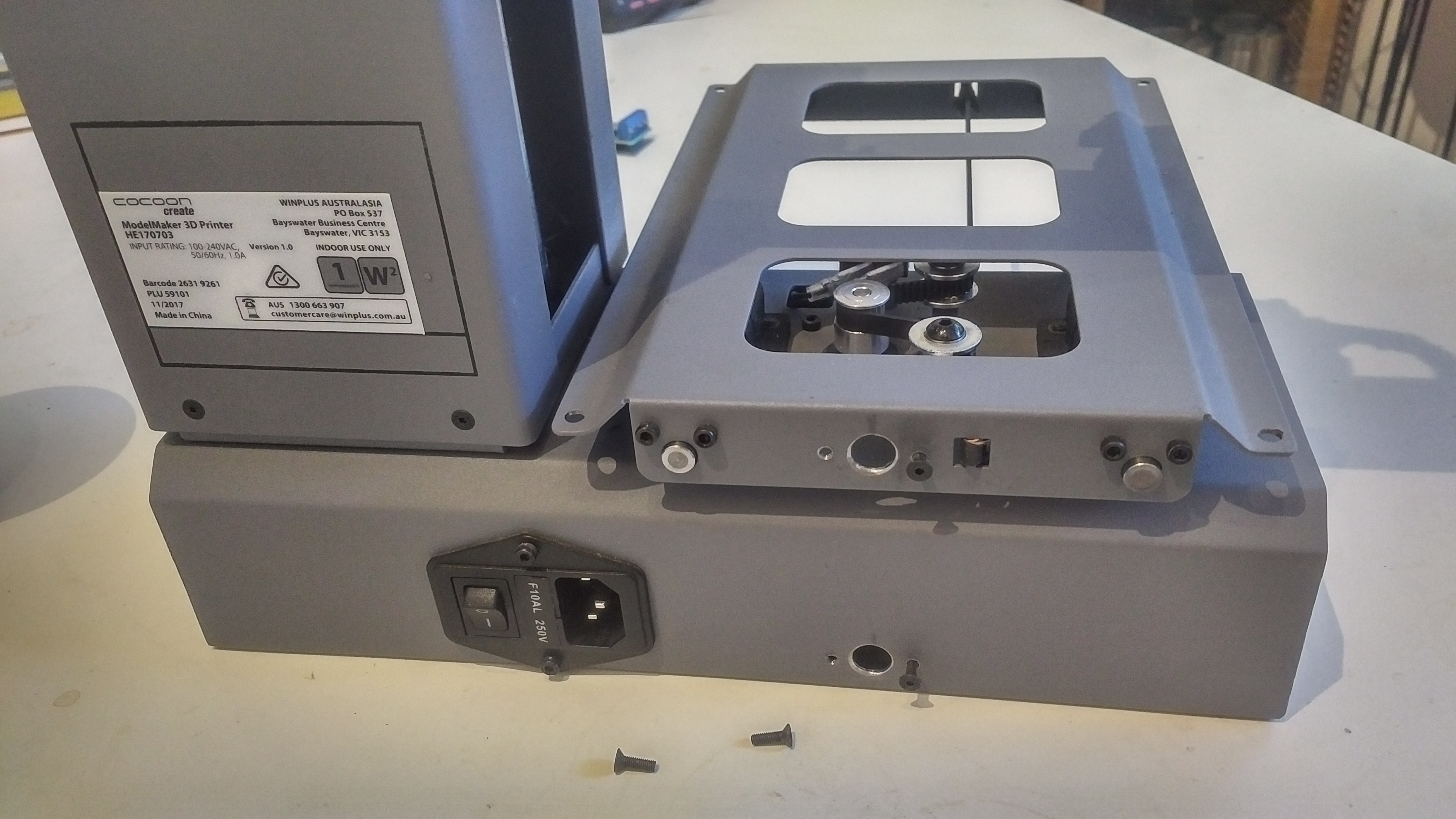
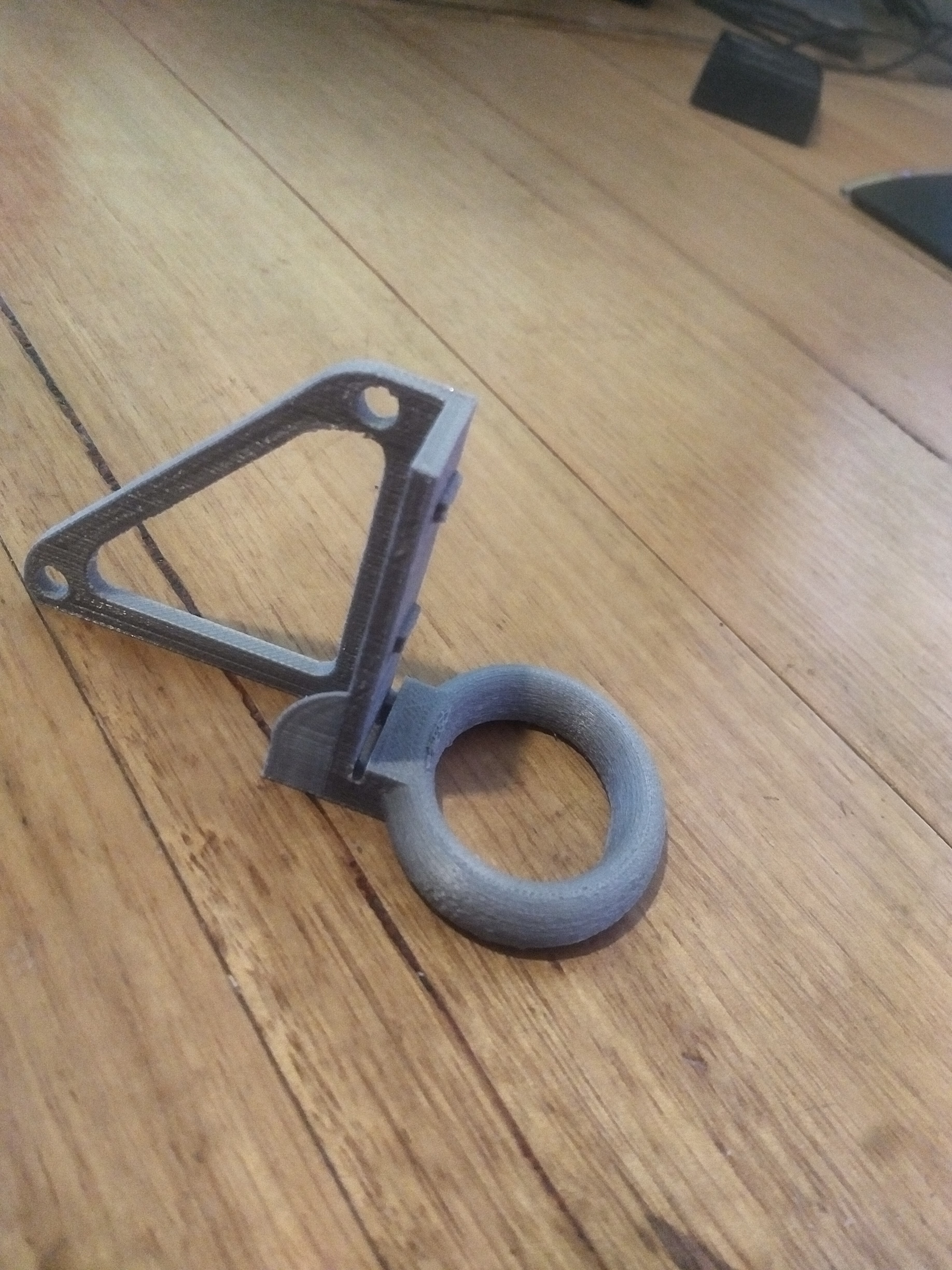
I designed and printed a nice little holder for the TRIAC board to prevent any live electrical parts making contact with the chassis. This holder is very secure and held in place with 4 M3 countersunk bolts with nylock nuts… it’s not going anywhere.
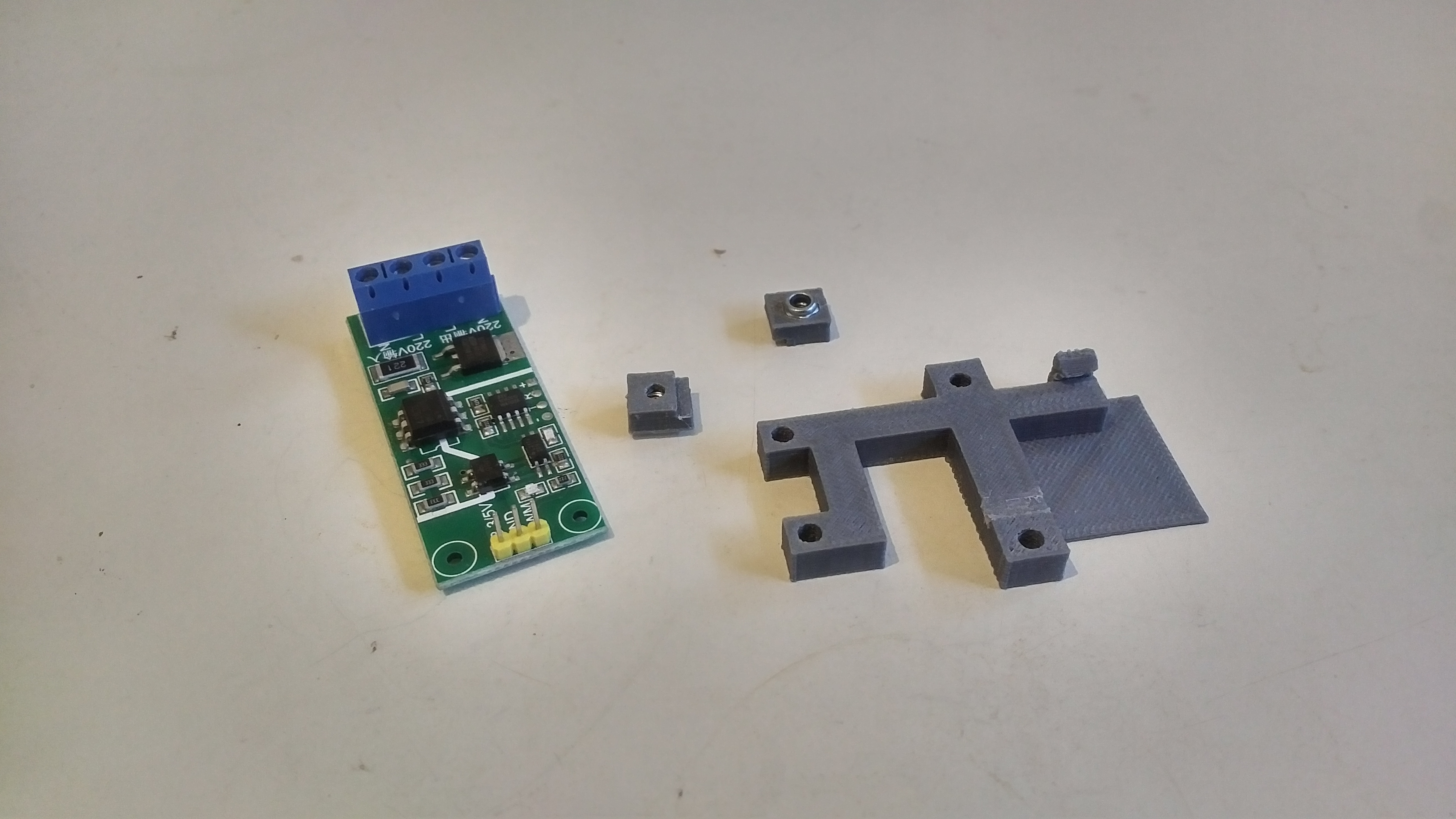
Just line the holder up on the outside of your chassis, mark the positions for the holes and drill away, then bolt the whole thing into place.
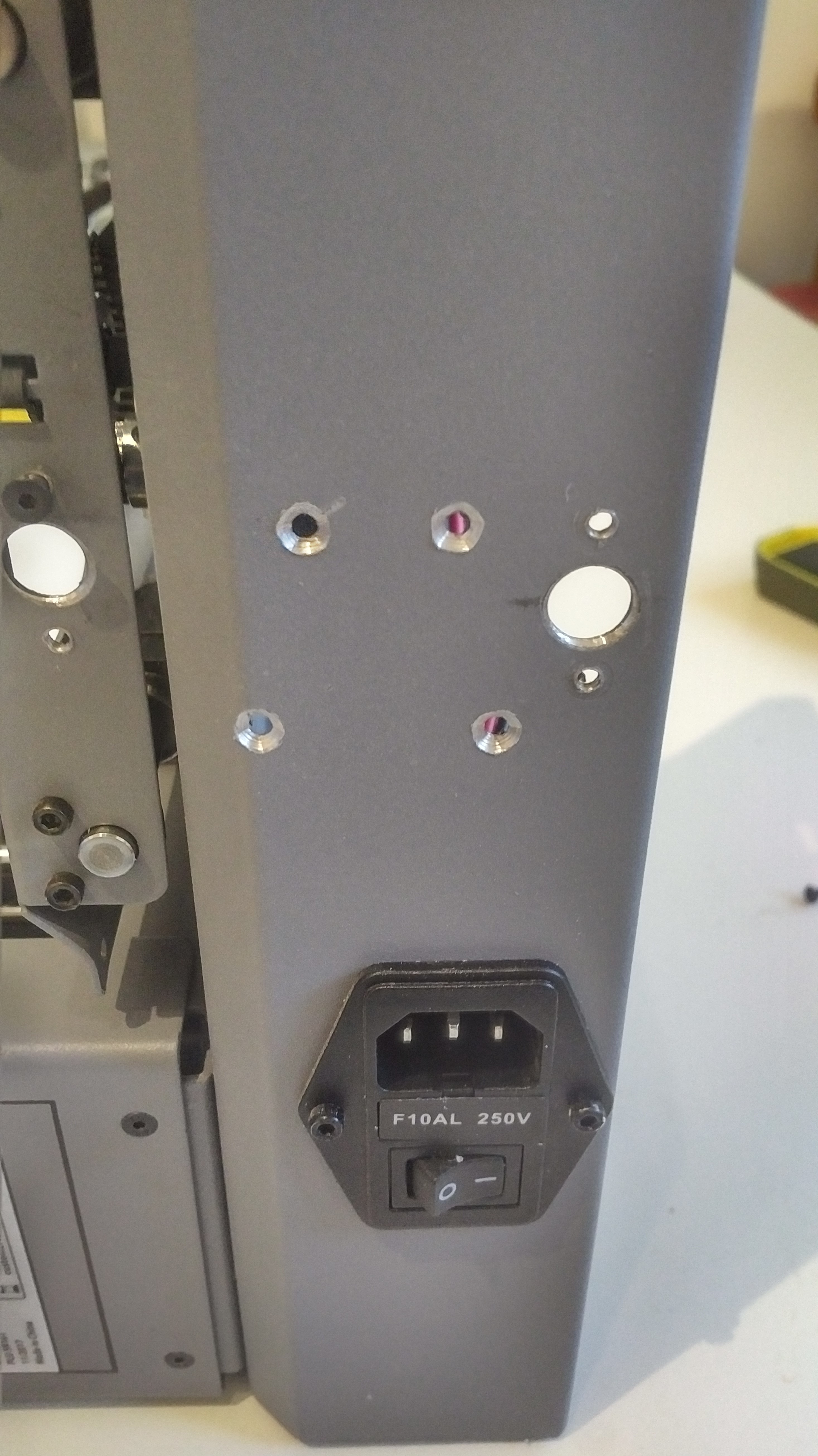
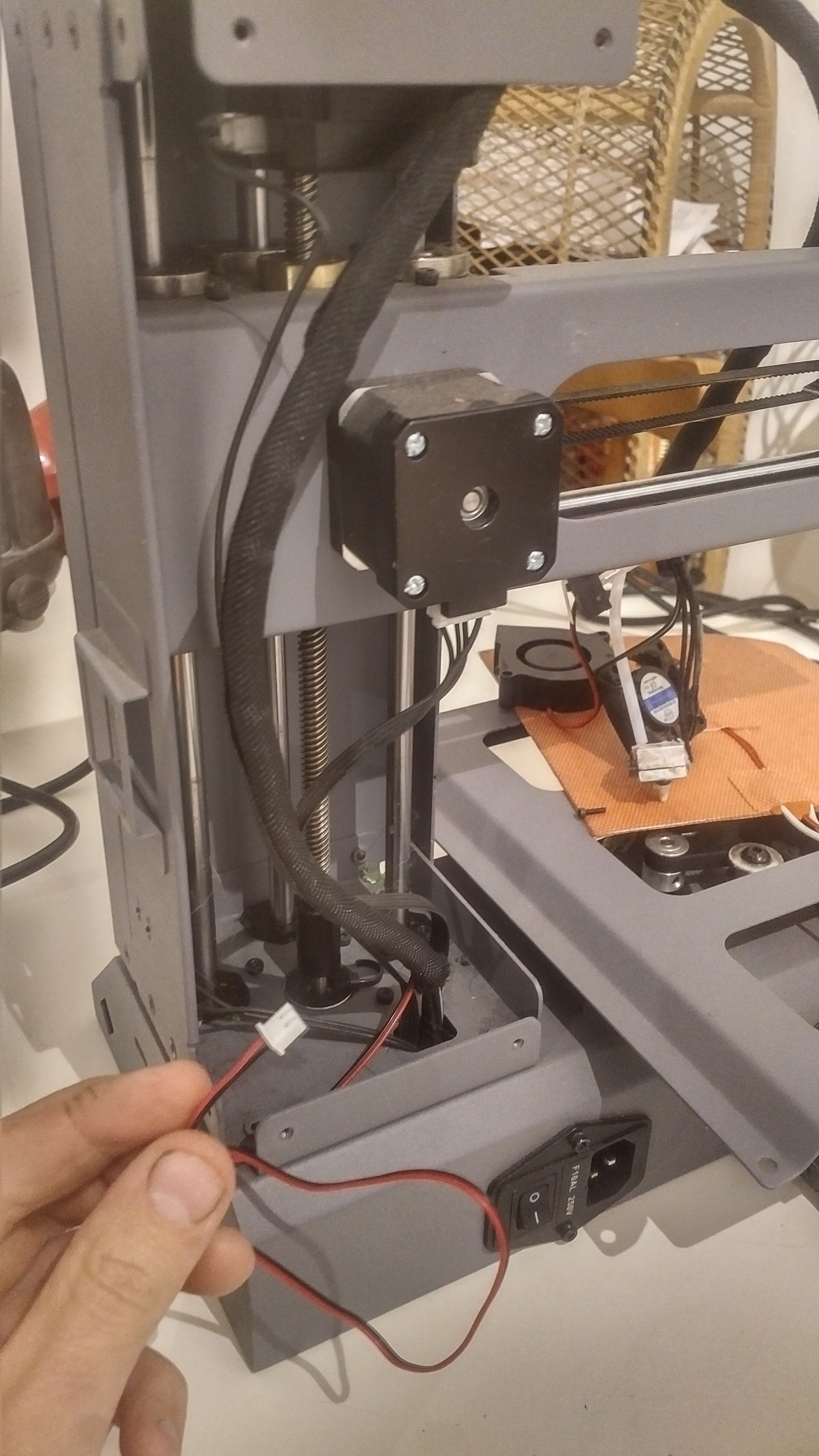
I then adapted the cable chains from my previous projects with some custom ends for attaching to the chassis. The cable chain ends have a sleeve/collar which prevents the wires chafing on the freshly drilled hole in the metal chassis.
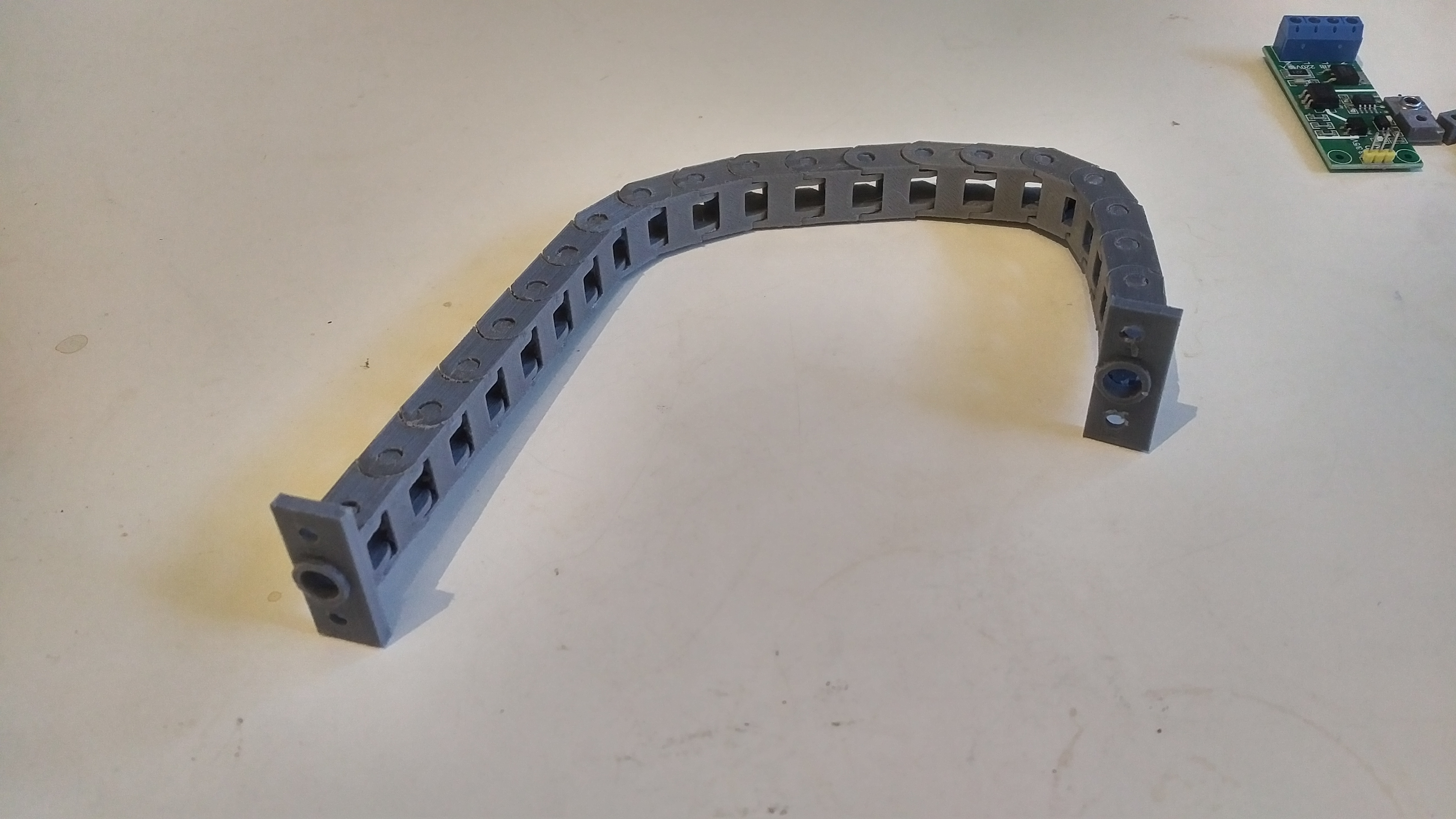
It’s then a matter of lining up where you want to position the cable chain and drilling more holes, 10mm for the cable entry and 2.5mm for the mounting holes, which you will then need to run an M3 tap through.
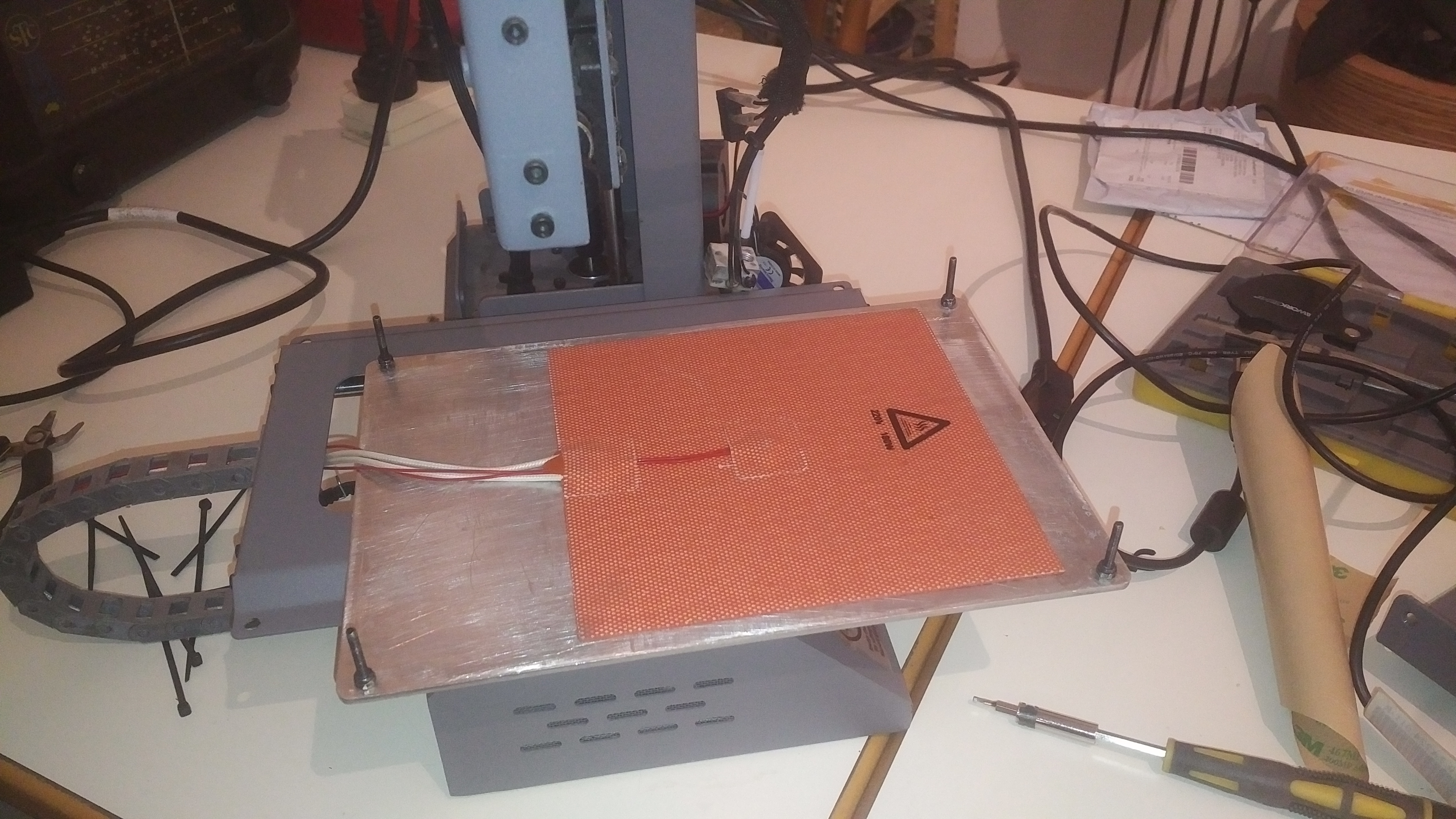
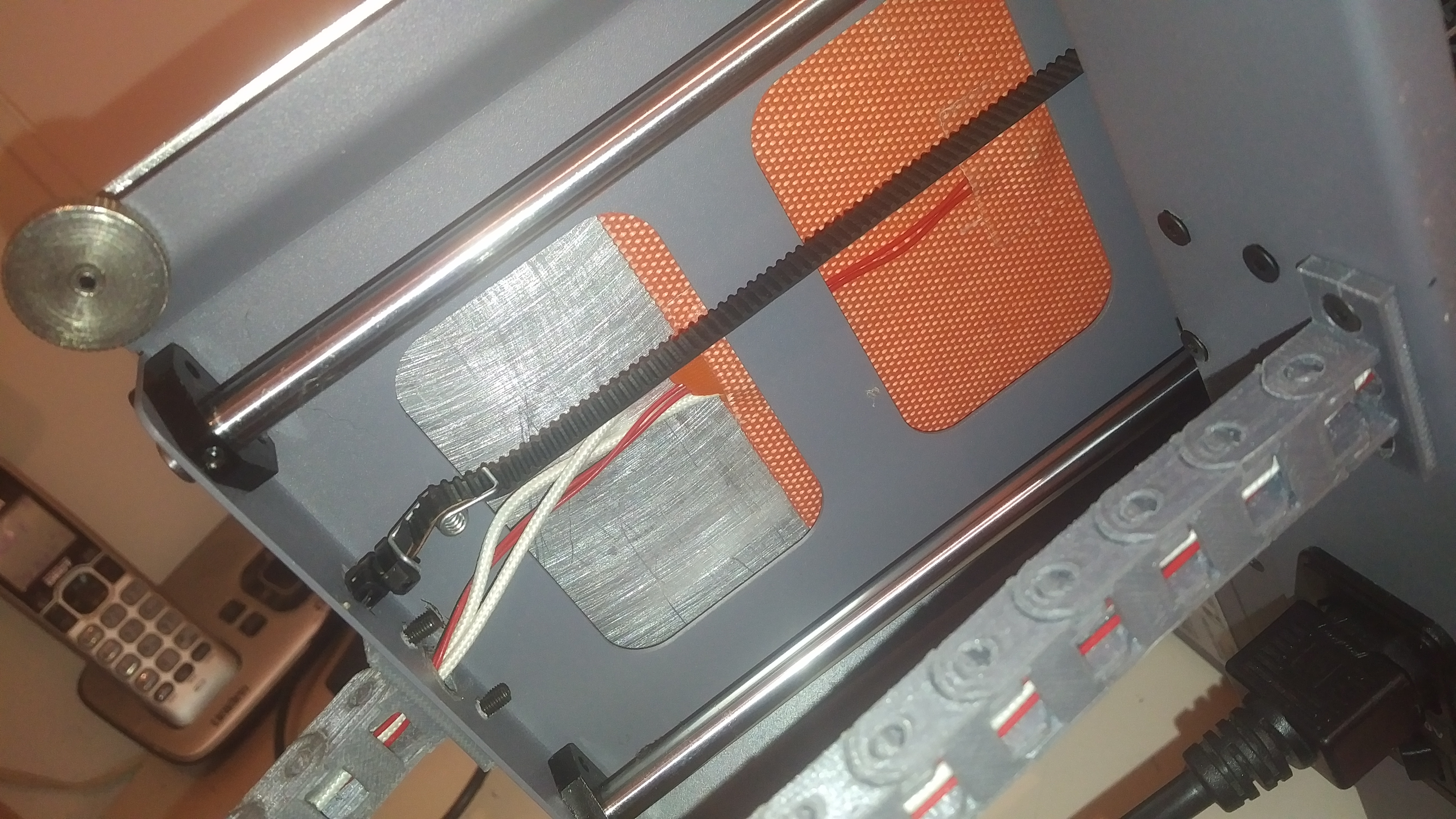
Attach the cable chain, thread the wires through and stick the thermal pad to the aluminium print bed. It’s probably a good idea to run a dedicated earthing strap/wire from the heated print bed to the chassis of the machine, but I haven’t due to the fact that I like living on the edge. Try to stick the pad directly under the printable area of the bed as there is quite a lot of wasted bed toward the back of the printer.
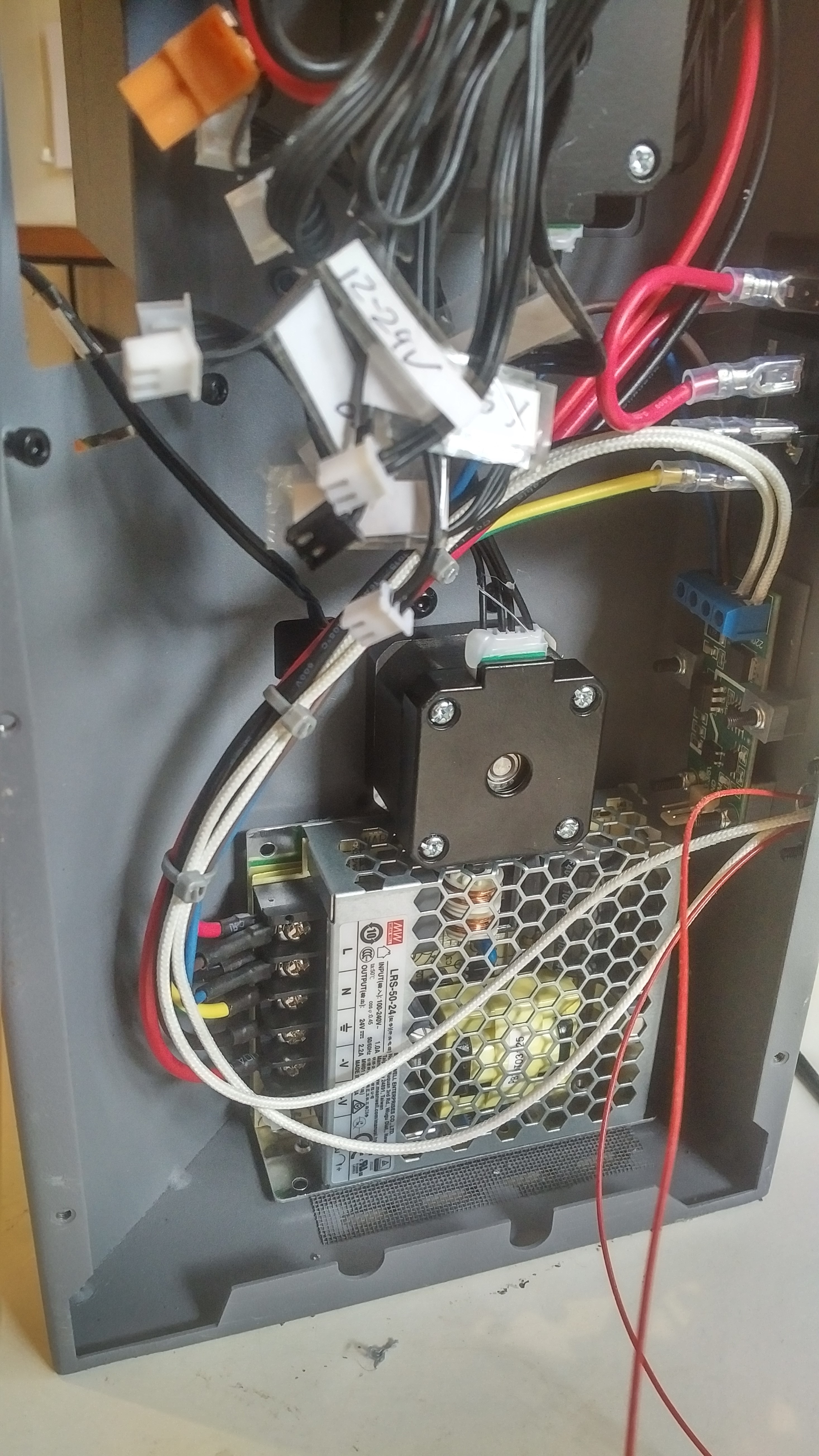
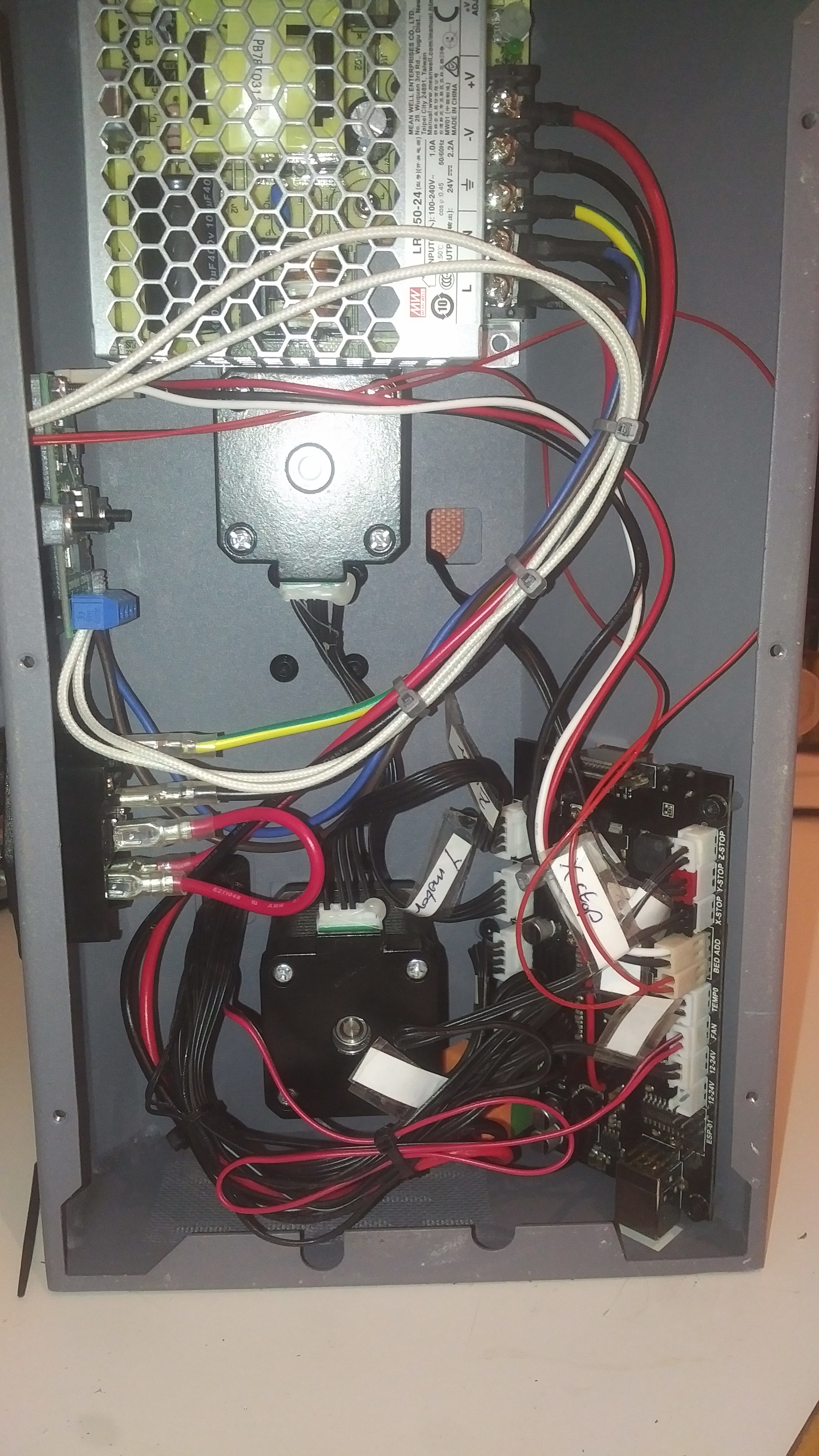
Now it’s time to do some wiring, I made up a loom using whichever connectors I had on hand at the time, but you could probably do the whole thing with dupont connectors and not have to solder a thing. The heated bed output from the board comes out at the pins directly under the “add” writing, with the far edge pin being the PWM signal, and the other being ground.
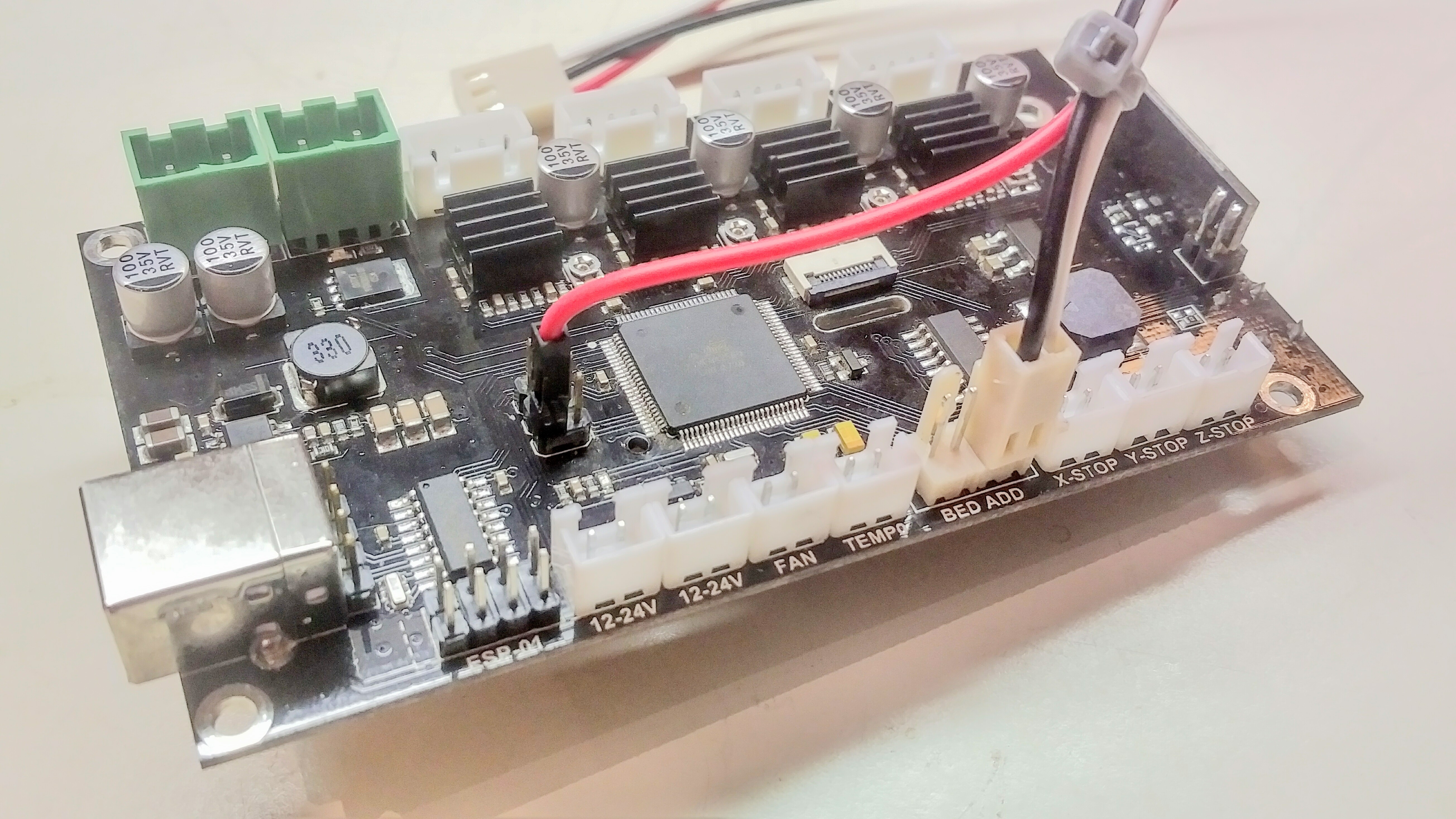
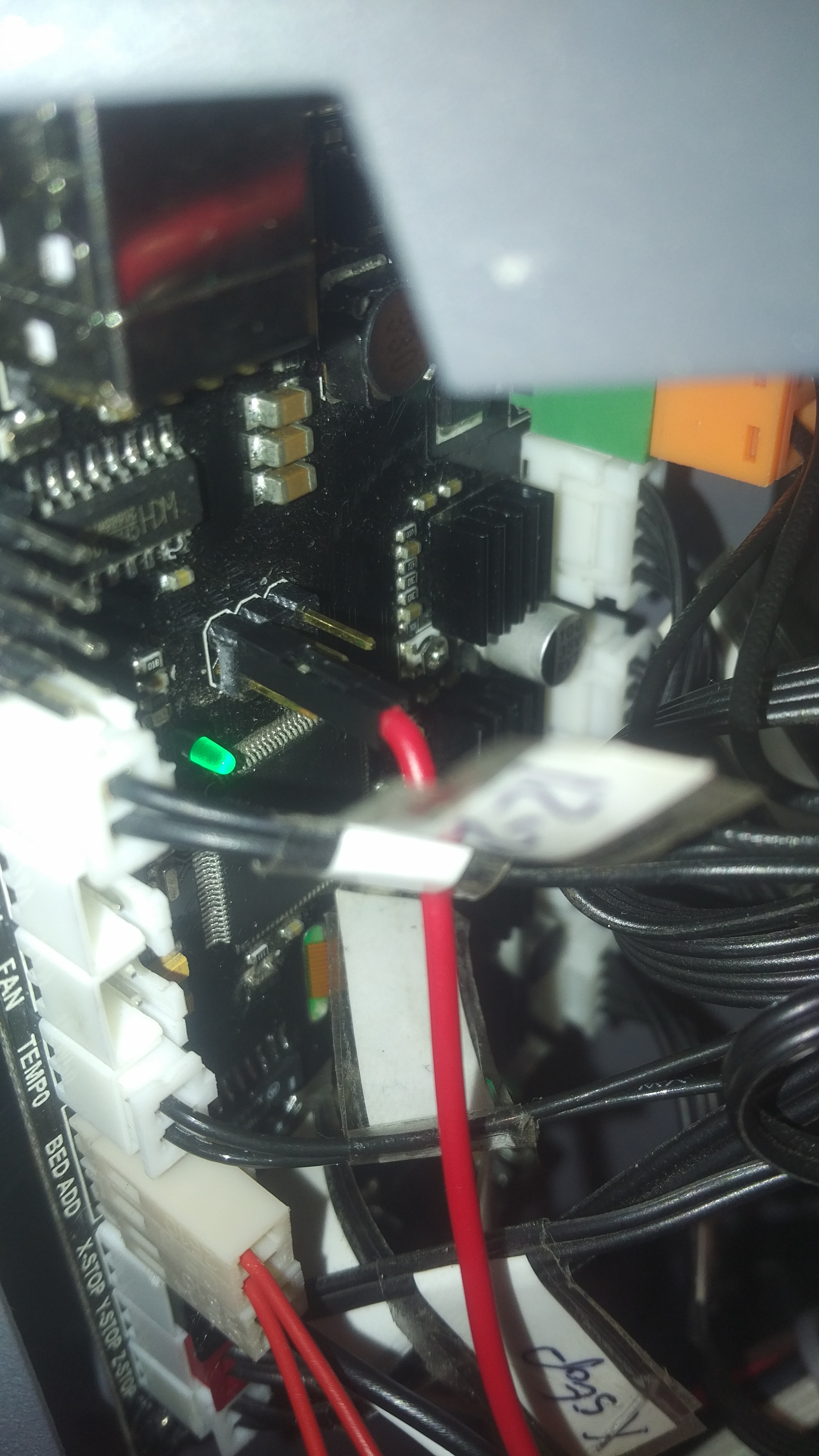
The 5 volt source voltage for the TRIAC module is tapped from the 6 pin header beside the arduino chip as seen in the picture.
The thermocouple plugs into the pins directly under the “bed” writing… for memory thermocouples are polarized, so you have a 50/50 chance of guessing this, or you could measure the output from the thermocouple using the millivolt setting on the multimeter to work out which is positive and negative. Then it’s just a matter of plugging in the TRIAC module, it’s very straight forward, ground goes to ground, 5volts from the motherboard goes to 3.3/5v, and the wire from the bed output goes to the PWM input.
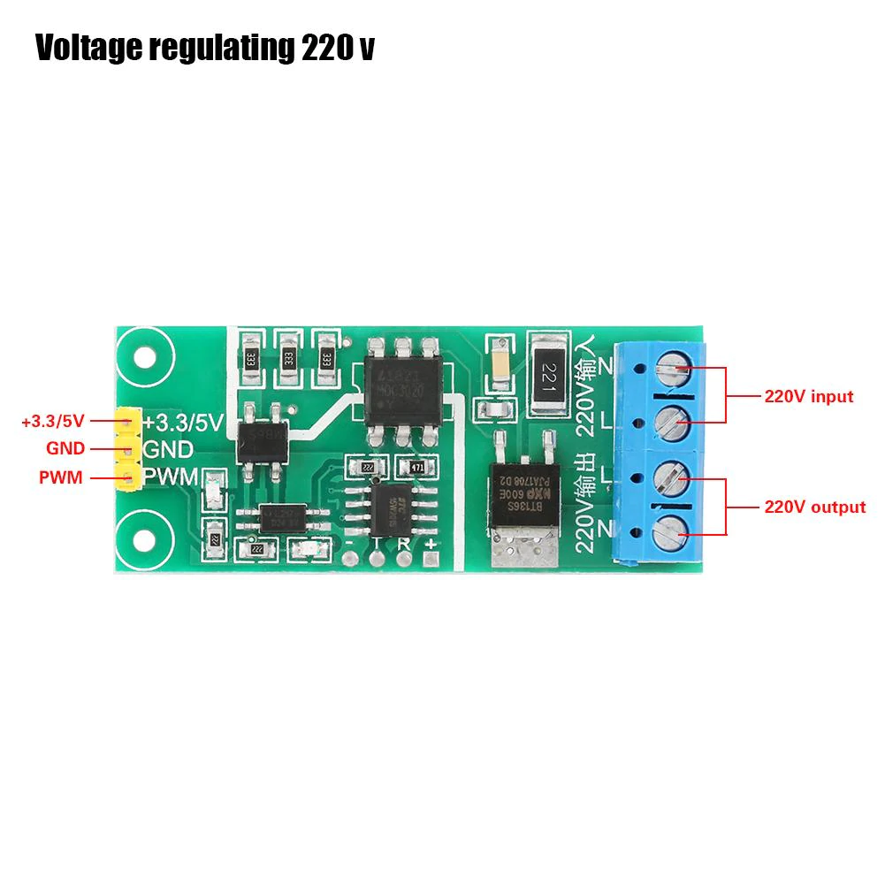
Then just connect 240 volts to the input of the TRIAC board and the connect the output directly to the heated pad, be sure to take your source voltage from after the On/Off switch, it’s actually much easier to take it from the input supply screw terminals of the power supply as seen in the picture.
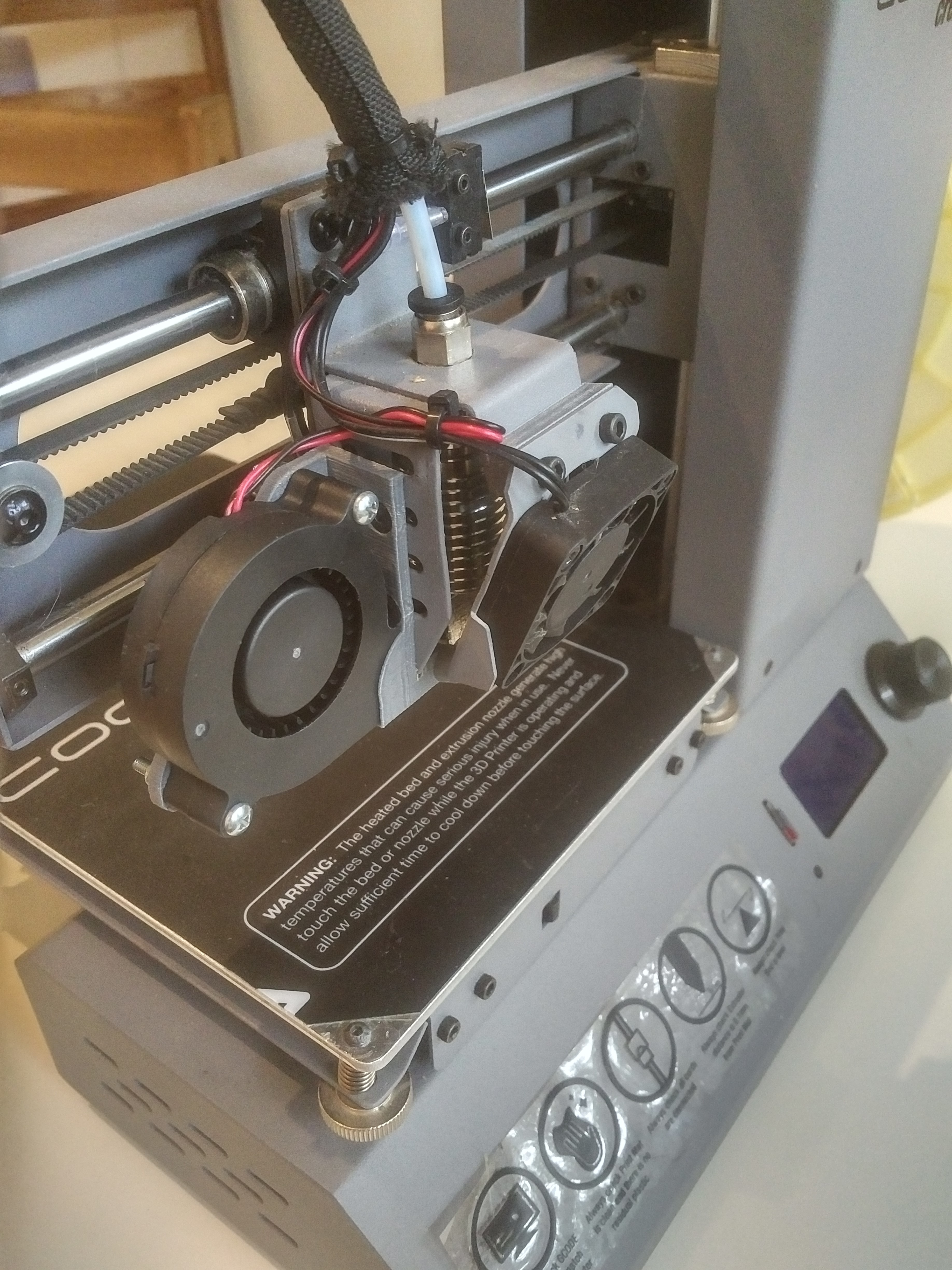
While I was inside the printer I decided to utilise the spare ‘Fan’ header to add a proper print cooling fan. I dug up an old 24 volt blower fan from a previous unfinished project and ran the cabled down the loom and into the printer from the print head.
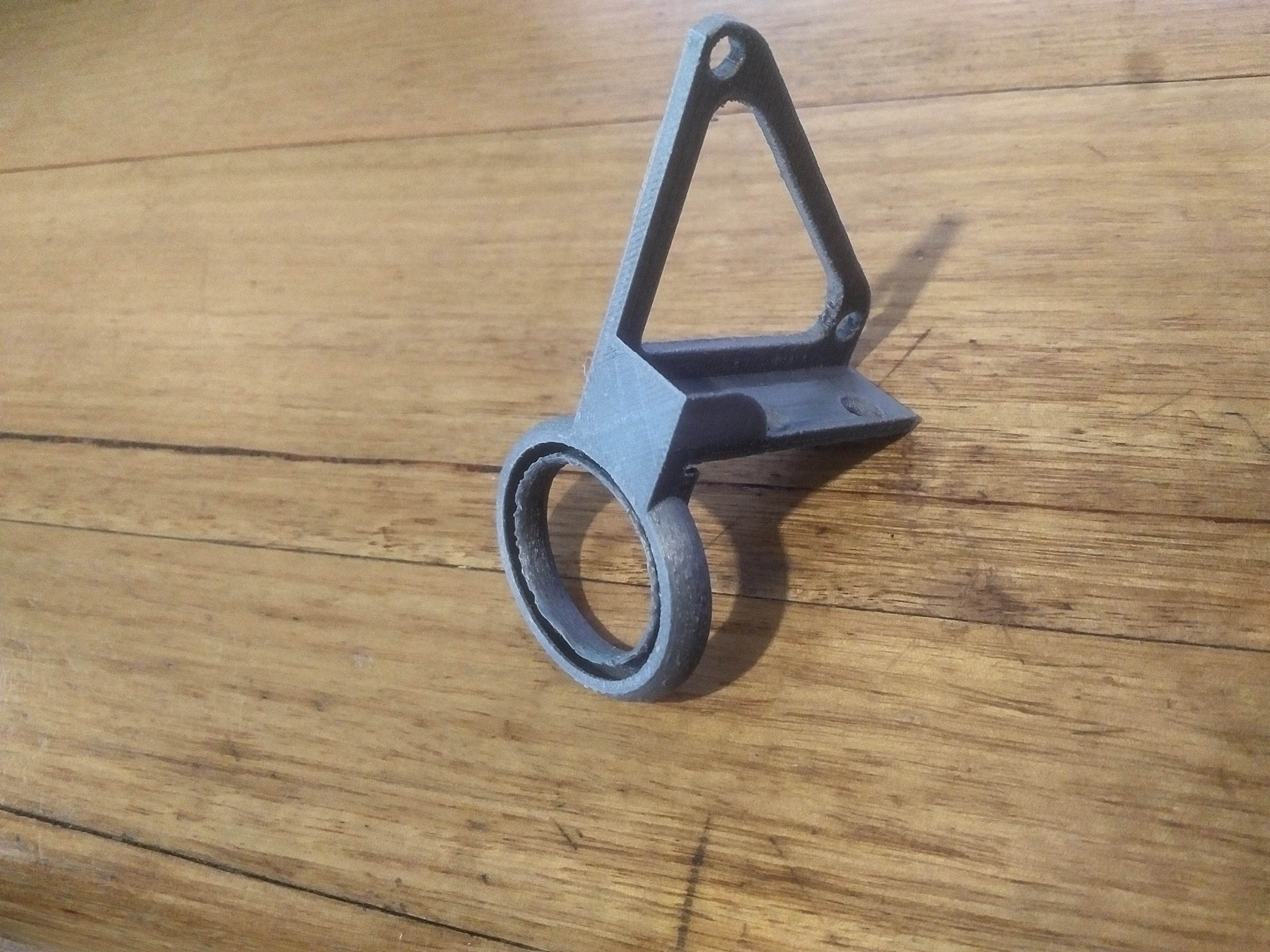
I printed up a single piece fan mount and outlet that fits onto the stock shroud. It doesn’t have a huge output due to some pretty big restrictions, but seems to do the trick! Just attack with a couple of countersunk M3 bolts and some nylock nuts.
While I was there I also added an all-metal hotend, and angled the original cooling fan to make it far more efficient. This involved fully cutting out the bracket behind the cooling fan to allow for full airflow, while also adding a printed spacer to allow for the new fan mounting angle.
For the heatbed and fan to work I loaded custom Marlin firmware and tweaked the code, but I won’t go into that as this guy has already explained it super well, and deserves credit. https://drucktipps3d.de/forum/topic/wanhao-i3mini-heatbed-mod/ There are also heaps of resources on github to help with tweaking the Marlin firmware, so it should all be very straight forward. The machine prints really well, and the heated bed performs perfectly with no calibration or tuning needed, you will be amazed at just how quickly it heats up compared to a DC powered bed.
As always here are the STL files for all the parts.
Hi, do you have a link for where to purchase the 220v triac module
Thanks
https://www.aliexpress.com/item/32988205235.html?spm=a2g0s.9042311.0.0.2d9c4c4dYrEXkO
Do you have a link to the heating pad you bought?
I couldn’t find the exact listing, but I got a 220 volt, 180 watt, square 150x150mm pad with the thermocouple included. This is the closest listing that I could find
https://www.ebay.com.au/itm/15W-1000W-110V-220V-Silicone-Heater-Heated-Bed-Pad-Heating-Mat-3D/143533526984?hash=item216b43cfc8:g:83UAAOSwEphcIH0t&frcectupt=true&autorefresh=true
Hello!
I’ve just completed these mods by copying the instructions, and have four tips to share – one very important safety tip!
Thanks for the great post, I’m so much more pleased with the printer now.
1) SAFETY! The PWM controller is set-and-forget. That is, it remains on whatever the last PWM signal told it to. So, if the bed happens to be heating at 50% at the end of a print, and the printer suddenly sets bed temp to zero, then the bed will keep heating at 50%. Same thing if you start heating and then change your mind, the bed will keep heating at 100%, and thermal runaway doesn’t seem to kick in. (I got to 110 degrees before chickening out.)
To fix this, add “BED_MIN_POWER = 2” in the firmware. This will send a very low signal to the controller and the bed will cool down as expected.
2) Firmware – TH3D 2.32 is different to the german forum linked to. Main gotcha is that PWM won’t work at all – no PWM signal sent – until you manually load in and then remember some default values for P, I, D using gcode commands. Then, PID control works great.
Here’s how I set up my Marlin firmware.
TH3d excellent guides, downloading and configuration of Visual Studio code here:
https://www.th3dstudio.com/hc/guides/programs/vscode-setup-guide-for-unified-2-and-marlin-2-firmware/
and firmware modifying, compiling and flashing here:
https://www.th3dstudio.com/hc/downloads/unified-2-firmware/information/how-to-use-unified-2-firmware/
In Configuration.h, uncomment:
#define WANHAO_I3MINI_V2
#define FAN_FIX
#define ENABLE_PIDBED
I also chose to uncomment #define POWER_LOSS_RECOVERY, however this is personal preference.
In configuration_adv.h, I also chose to uncomment #define BABYSTEPPING, this is also personal preference.
In Configuration_backend.h, in the section “#if ENABLED(ENABLE_PIDBED)”:
#define MAX_BED_POWER 250 // was 25
#define MIN_BED_POWER 2 // New line. If set to zero, the controller retains last value. I tested and setting the pin 44 to PWM 1 for 15ms is sufficient, for the board I have.
3) Connecting the PWM module – when it’s upside down and backwards in the bottom of the case, it’s hard to remember which is the input and which is the output. The board is not labelled clearly. Check from the listing where you bought it, and make sure to wire correctly!
4) Fan mount – I printed mine in PLA, well before doing the heated bed mod. With a silicone sock on the heat block, the room is very tight. More importantly, the ring starts to droop and drags on supports and other thin structures. I ended up using epoxy to attach some steel wire to the far end and hook it up to the metal on the far side.
Also, in my slicer I’m getting good results with fan speed 50%, printing pla. It seemed like 100% may have been too much, giving lower layer adhesion and sometimes blowing thin walls away from vertical.