A friend of mine is trying to find ways of turning e-waste into education devices, one source of e-waste that is ridiculously common while also yielding heaps of parts are desktop printer/scanner combos. You see them thrown out virtually everywhere. The neat thing about them is that they use optical encoders to drive DC servo motors, so they are relatively easy to interface, and unlike stepper motors they can accelerate rapidly and never loose steps. The optical encoders are the clear plastic strips that you see suspended behind the ink cartridge, the optical sensor behind the print cartridge reads these outputs so as to know exactly where the head is at any given time. Luckily these outputs are simple digital interrupts and there are countless Arduino libraries out there working with them. There are also geared DC motors with rotary optical encoders built into them, I used one to rotate the turntable.
I designed the mechanism and concept of this very ghetto X, Y, Z gantry hoping that it could be adapted for lots of different purposes. Initially it was to be used as a hot wire foam cutter, but I can’t see any reason why it could’t easily be adapted to 3D printing as well.
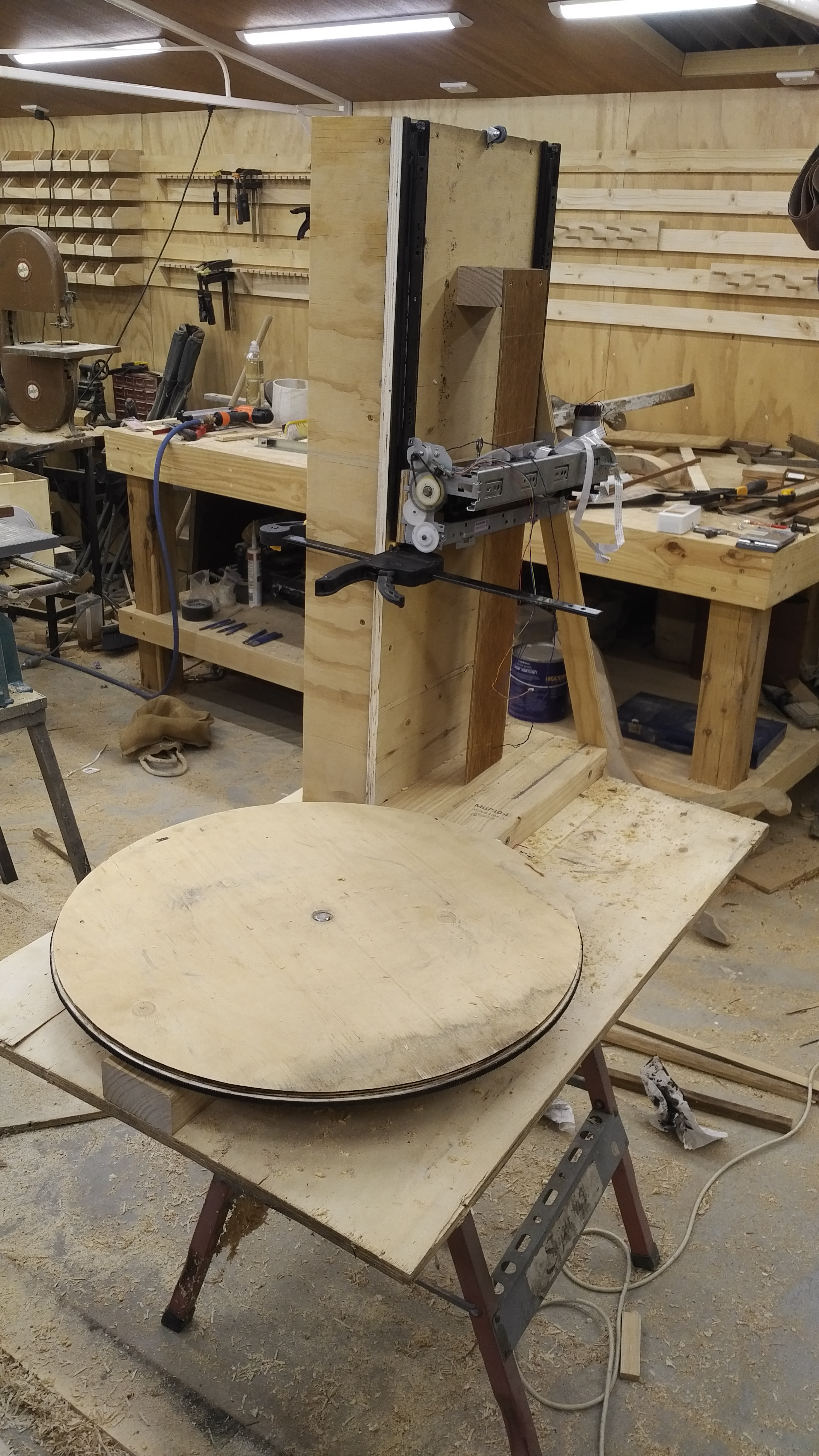
The machine is built from plywood that I salvaged from old packing crates. The turntable has been cut into a perfect circle using a router pivoting around the center point, with a second rebate around the perimeter about 4mm proud for the belt and pulley arrangement to align with.

The drive motor is directly coupled to the belt that has been epoxy glued directly onto the turntable, however due to slight variations in tolerances I have spring loaded the motor onto the belt so as to prevent any possible skipping.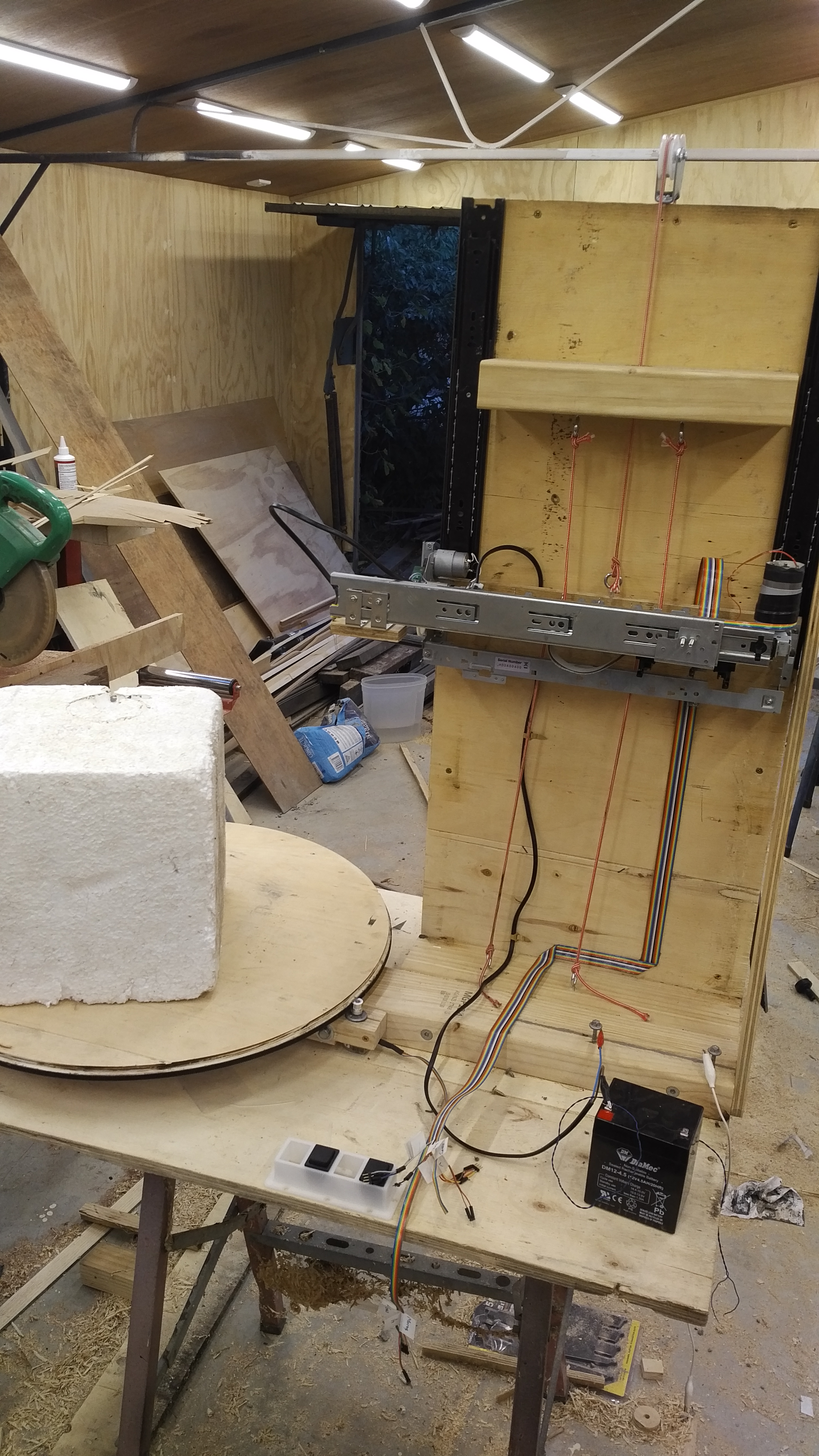
The gantry is very straight forward, an IKEA drawer runner is simply pop riveted onto the old printer frame, while the sliding component is coupled to where the old print cartridges used to mount. The whole gantry moves vertically up and down using cord that has been wrapped 3 times around the old paper feeding rollers. it is important to wrap the cord around the rollers 3 times in order to avoid slippage (there is some theory to this that you can google if you are interested).
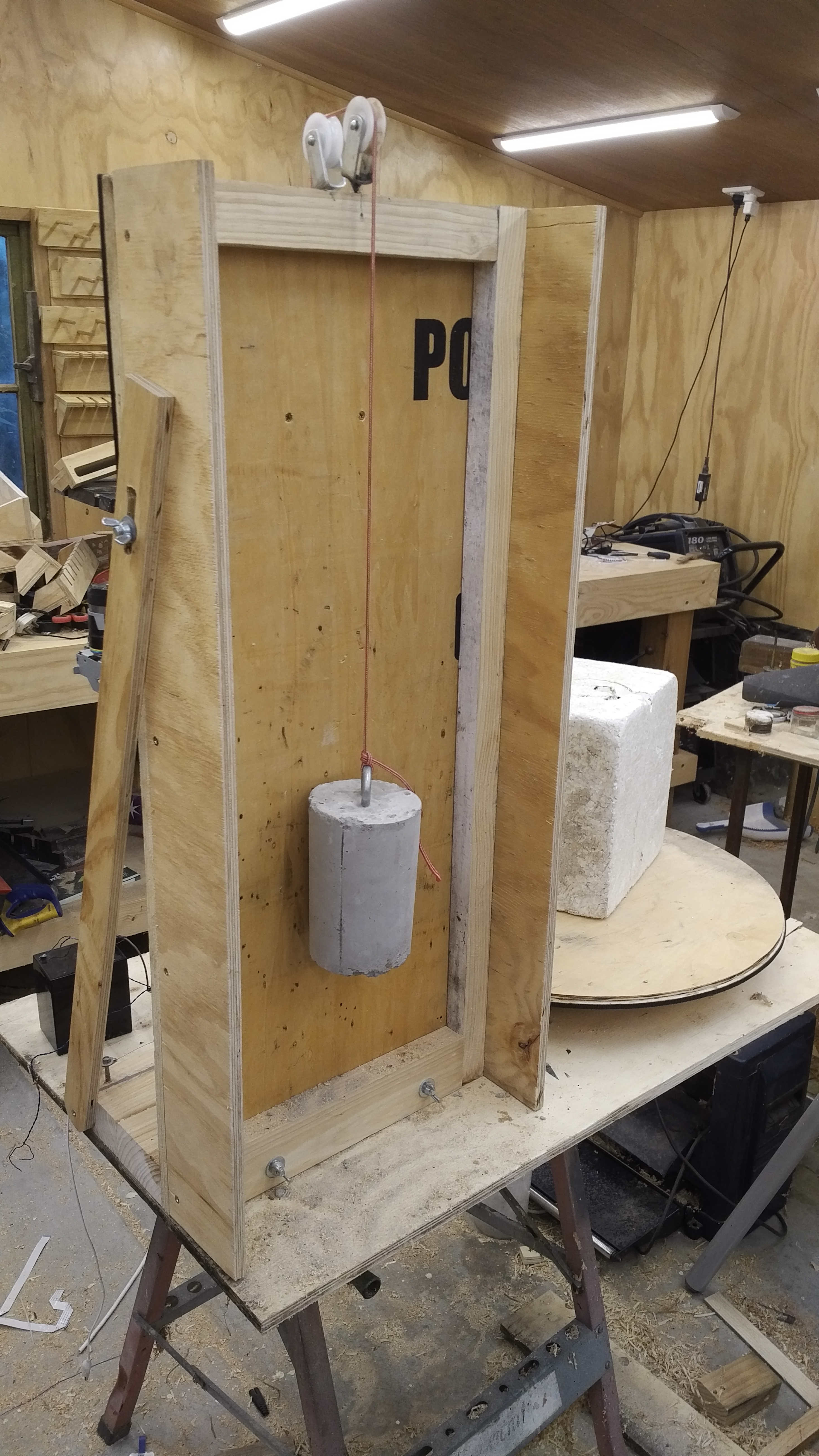
A counterweight made from cement with an eye bolt cast into it balances the whole mechanism.
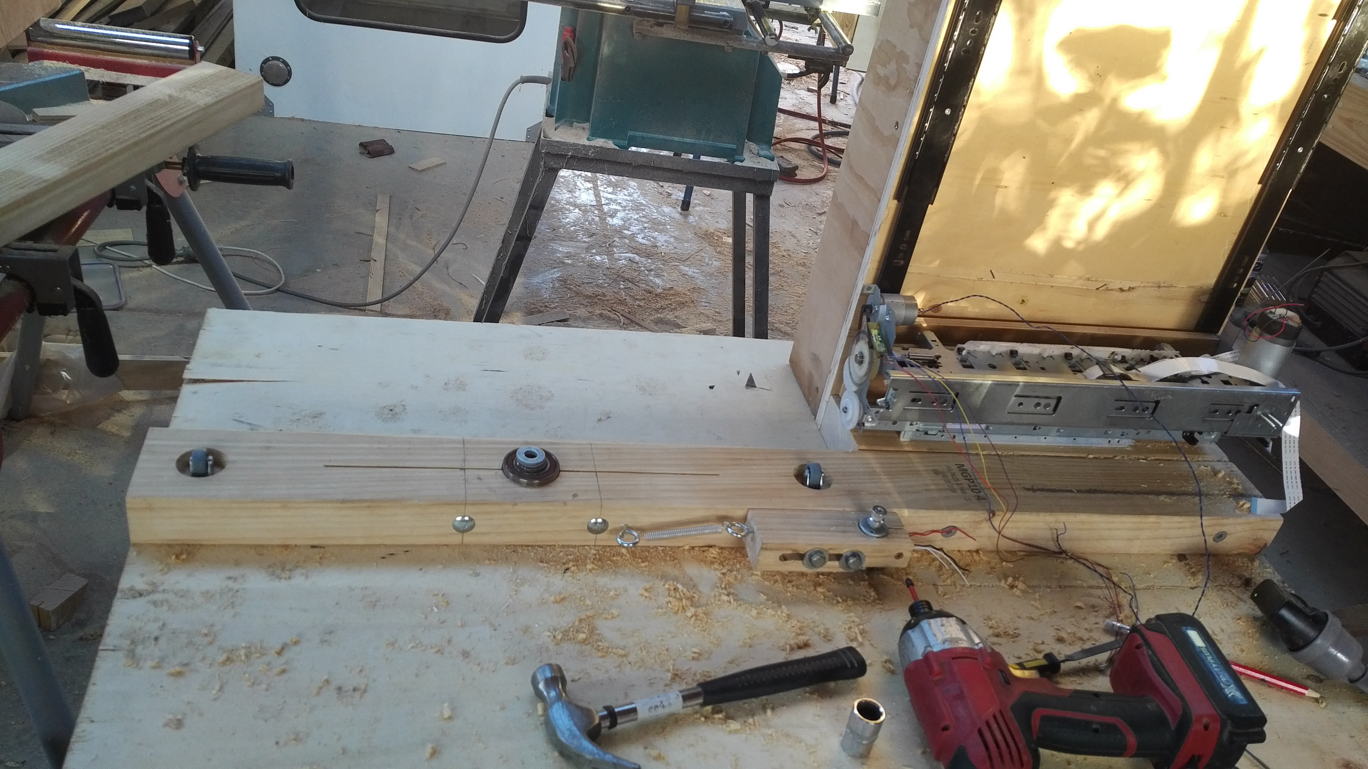 The turntable is aligned using two castors under a tiny bit of pretension, and a ball bearing in the center as the pivot point.
After wiring up the outputs for the optical sensors, I handed the project over to a tech student at RMIT who connected it to an Arduino Mega using a H-Bridge for each motor and the 6 interrupt pins on the Arduino to read the optical encoders. Sadly 6 is the maximum number of interrupts that an Arduino Mega can handle, luckily 6 is all we need to drive 3 servo motors from 3 optical sensors. I think he did a fantastic job of getting the whole thing running and proving the concept, and all of the videos of it working are attributed to his great work.