This basic direct current electric motor has been designed with simplicity and ease of construct in mind, as such there are a minimum of parts and requires no soldering. This makes it an ideal classroom or children’s project.
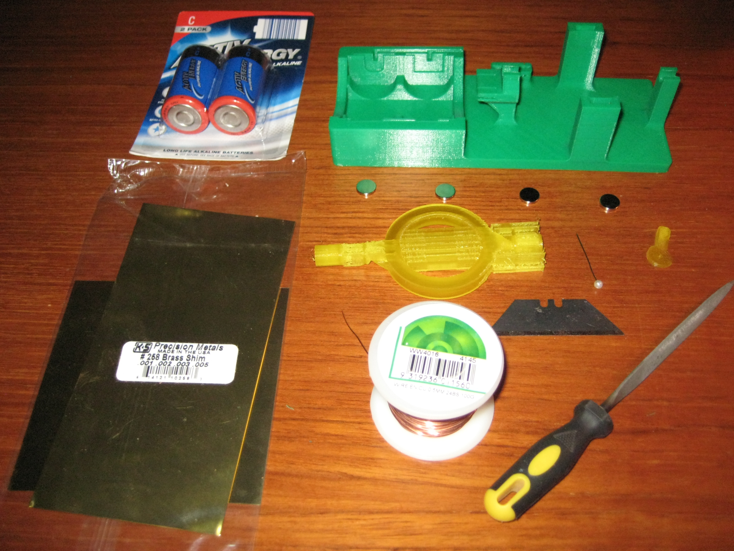
The project consists of only 3 printed parts, four 2x10mm neodymium magnets, 2 C cell batteries a spool of 0.5mm enameled copper wire, a sewing pin, a thumbtack and 9 contacts made from 0.002 and 0.005 brass shimming.
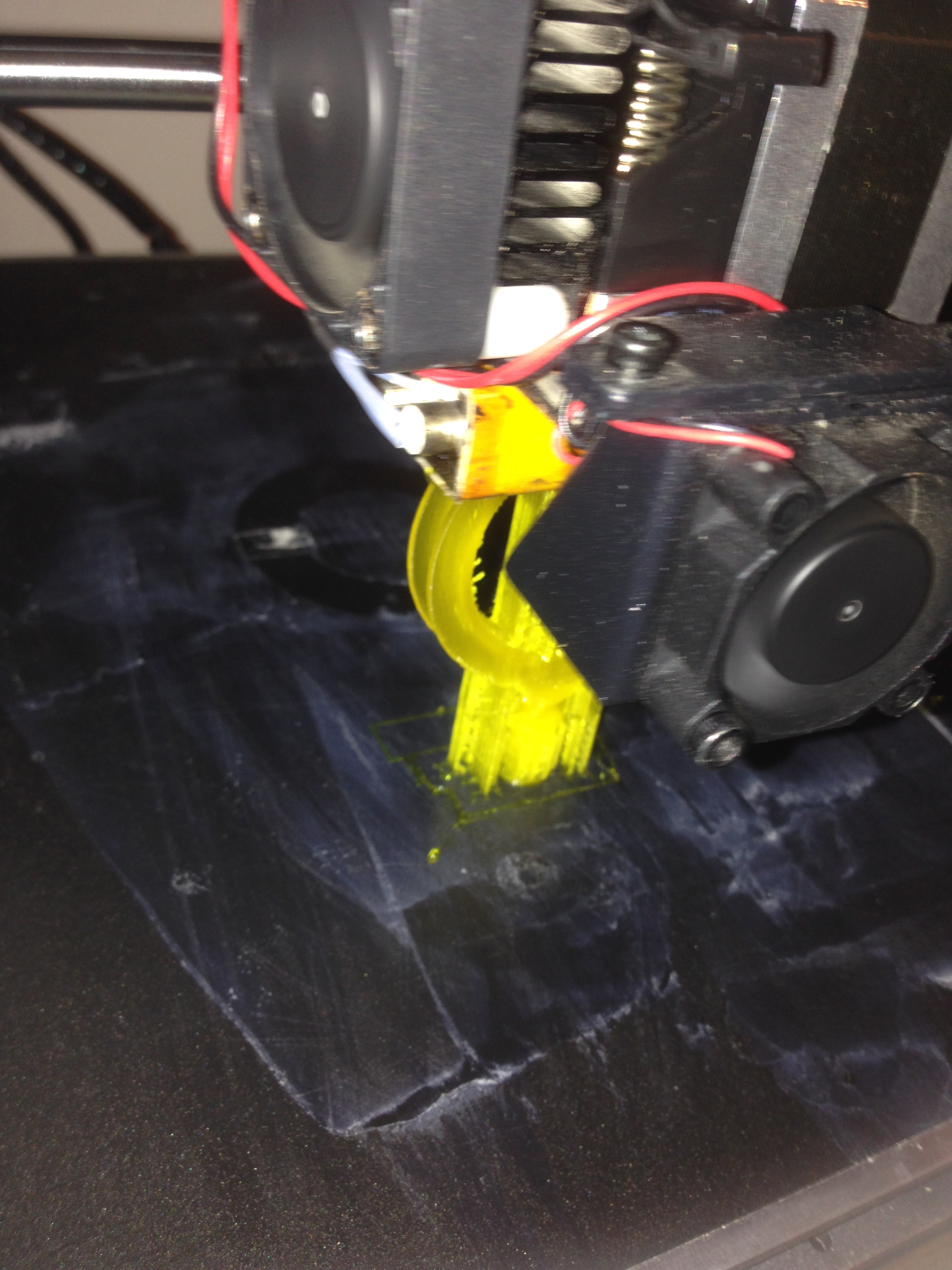
For simplicity the armature frame is combined with the bearing shafts and commutator as a single piece. The armature should be printed vertically with 100% infill, supports turned on everywhere and set to a high print quality. The switch can also be printed at the same time.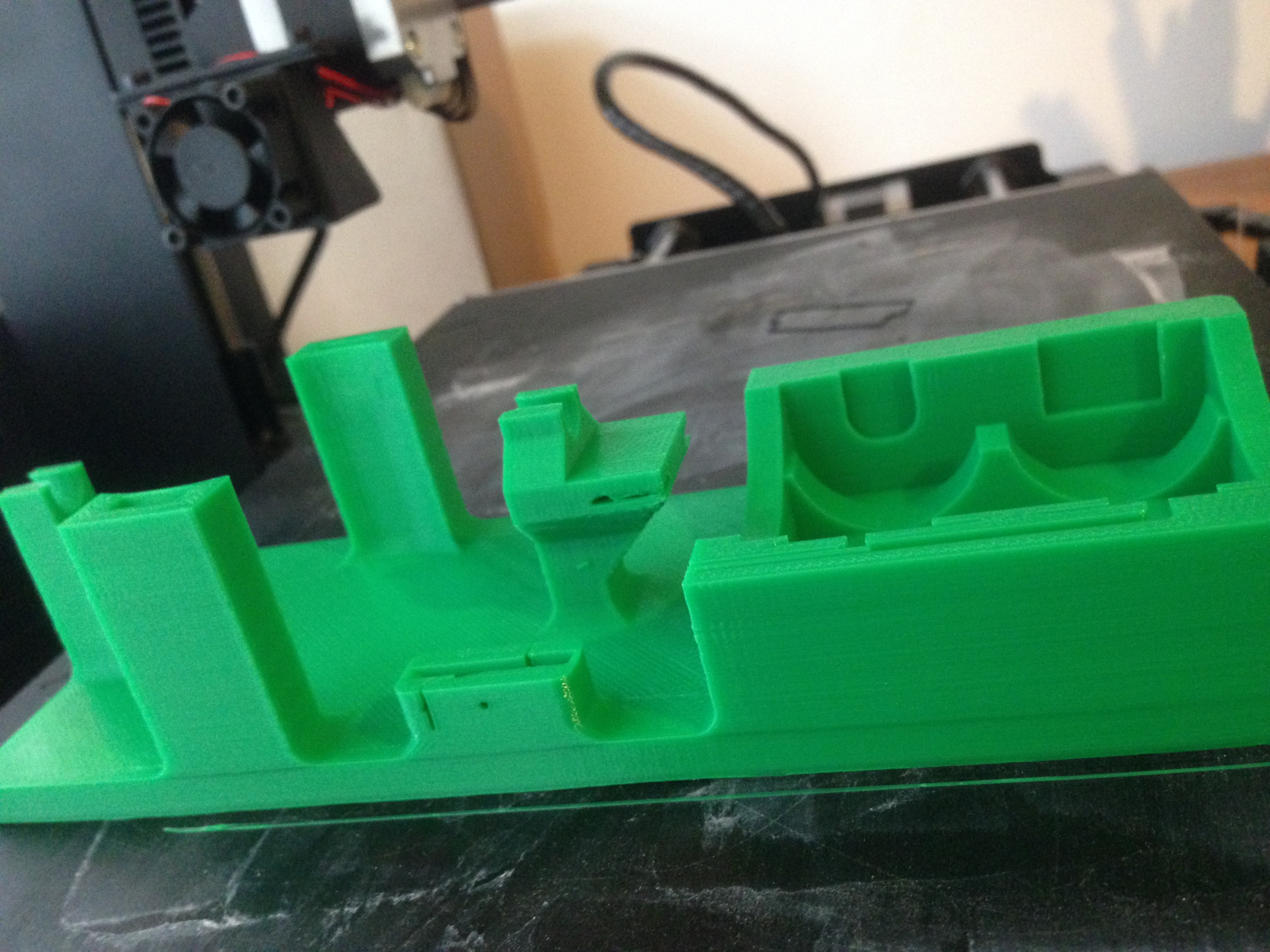
The base of the motor combines the battery holder, switch, bearing surfaces and magnet holders into a single piece. When printing, good results can be achieved with no supports, 25% infill and a 0.8mm top layer thickness.
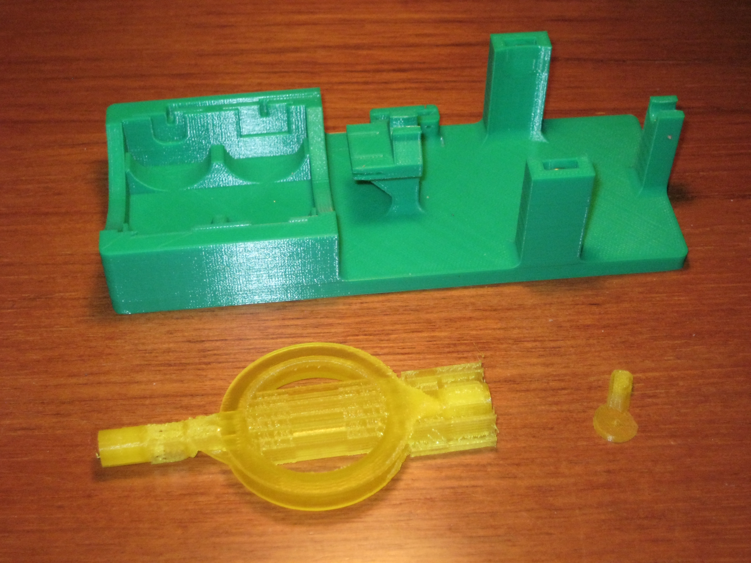
Once the base has finished printing the grooves will require cleaning out with a fine blade, the horizontal brush holder grooves will need the most attention. The armature will need the supports trimmed off with a sharp hobby knife and the bearing surfaces smoothed out with a file or fine sandpaper.
To keep things simple all the contacts in this project are made from brass shimming, it can usually be bought from arts and hobby stores quite cheaply in small assortment packs. For this project all the contacts with the exception of the brushes are made from 0.005 shimming, while the brushes are made from the thinner 0.002 shimming. If brass is difficult to come by, the fine tin from the base of a Milo can should do the trick.
Using the templates provided cut and bend the brass shimming into the required shapes. When bending the shims use a ruler or straight edge along the dotted line and bend up.
To construct the armature remove the build supports and clean out the grooves in the commutator with a thin blade. Then slide the brass commutator shims into the grooves. If the brass contacts are loose on the commutator use a dab of epoxy or super glue under the shim to hold them in place.
To wind the coil, feed the end the wire from your spool through the hollow shaft from the inside of the coil to the outside until it protrudes about 5cm from the end. Then start winding the wire around the armature frame, this is made easy by the sides of the frame being open at each end. Once the wire windings are flush to the edge of the plastic frame cut the wire generously and feed back though the hollow shaft alongside the first wire.
Cut both wires off to 3cm and bare the insulation from the first 7mm of each end with a sharp hobby knife. Then poke the wires into the small holes beside the commutator contacts, it might be necessary to clean the holes out with a hot pin before the wires will fit.
To complete the base, slide the brass shims into either end of the battery holder and switch housing. With the switch it is necessary to put a slight bend on the long brass contact so as to add a little preload onto its adjoining contact.
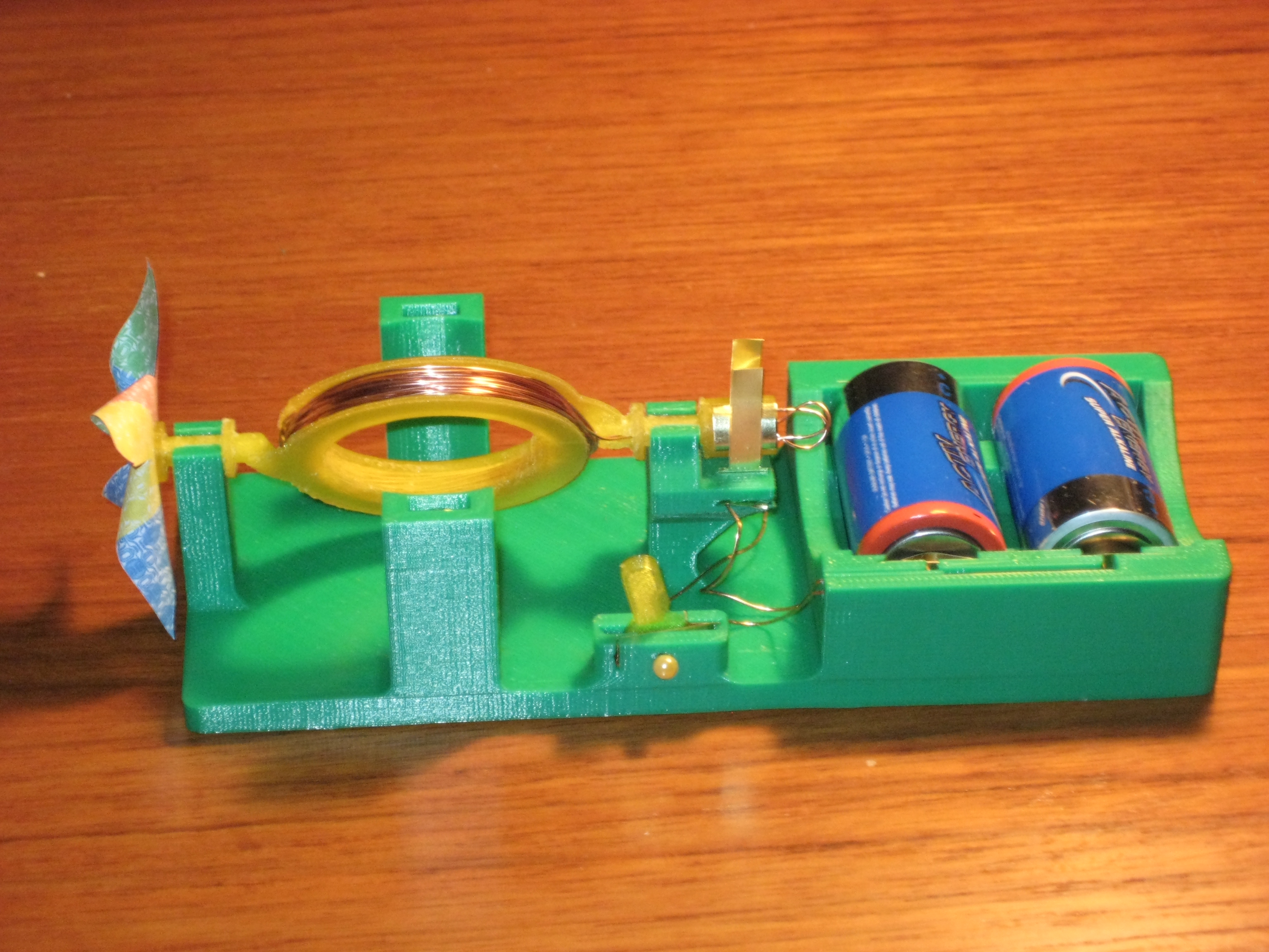
Cut two 12cm pieces of copper wire and a 9cm piece and scrape the insulation away from the first 7mm on all ends. Insert the bare ends of the long wires behind the battery tabs and feed through the channel as show in the picture. Poke the ends of the wires into the small provisions in the switch and brush connectors. Again it might be necessary to use a hot pin to clean out the holes beside the contacts. Use the shorter piece of wire to connect the second brush contact to the second switch contact. There should be enough tension to securely hold the wire against the brass terminals and switch contacts.
The motor uses two 2x10mm neodymium magnets stuck together on each side. They should fit snugly into the cut-outs in the magnet holders, but a touch of glue is helpful in stopping them from vibrating during operation. The switch lever just slides down into the provision and a pin is used as the pivot. Cut the sharp end off the pin and bend using a pair of pointy nosed pliers to secure the lever.
Before installing the armature into the base it will be necessary to put a little bit of inward preload onto the brushes, this will keep them in good contact with the commutator contacts. Once that’s been done it’s a simple matter of popping the armature into the bearing blocks, this will require a little bit of force as there is a tiny but of interference to hold the armature in place.
Finally put the batteries in and flick the switch, the armature will require a gentle spin to get going. You should now have a working DC model motor. A drop of vegetable oil on each bearing will help the engine run smoother and quieter.
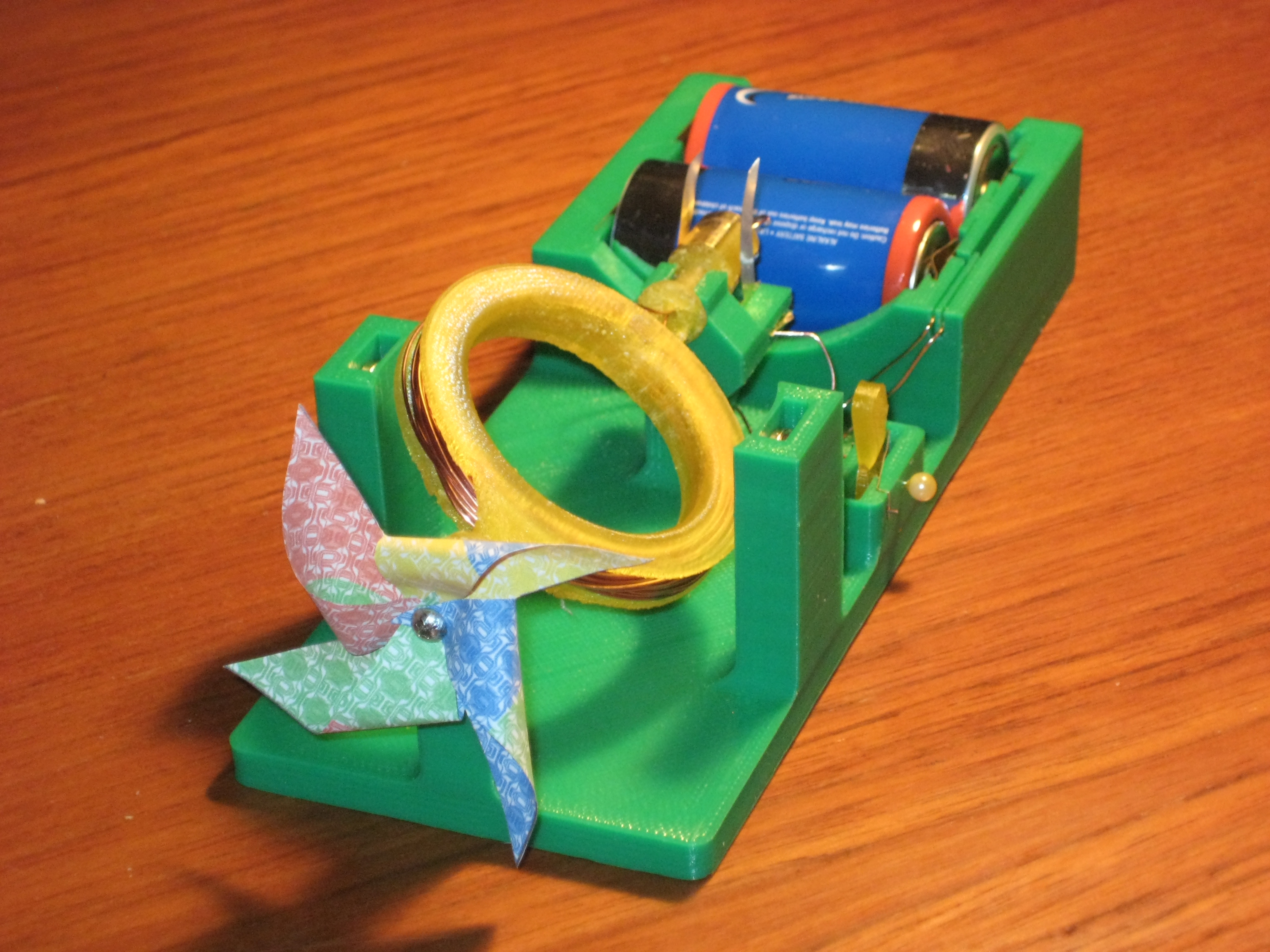 Once you’re happy with its operation you can use a small screw or thumbtack to attach the pinwheel to the end of the shaft.
A link to the instructions pdf for the project
And as always all the STL files required