Because of current world circumstances I’ve been forced to spend much more time tinkering in my workshop with far less income than is required for building kickass projects. However I’m relatively resourceful, hoard lots of materials and am rather good at scrounging, so I managed to keep myself occupied.
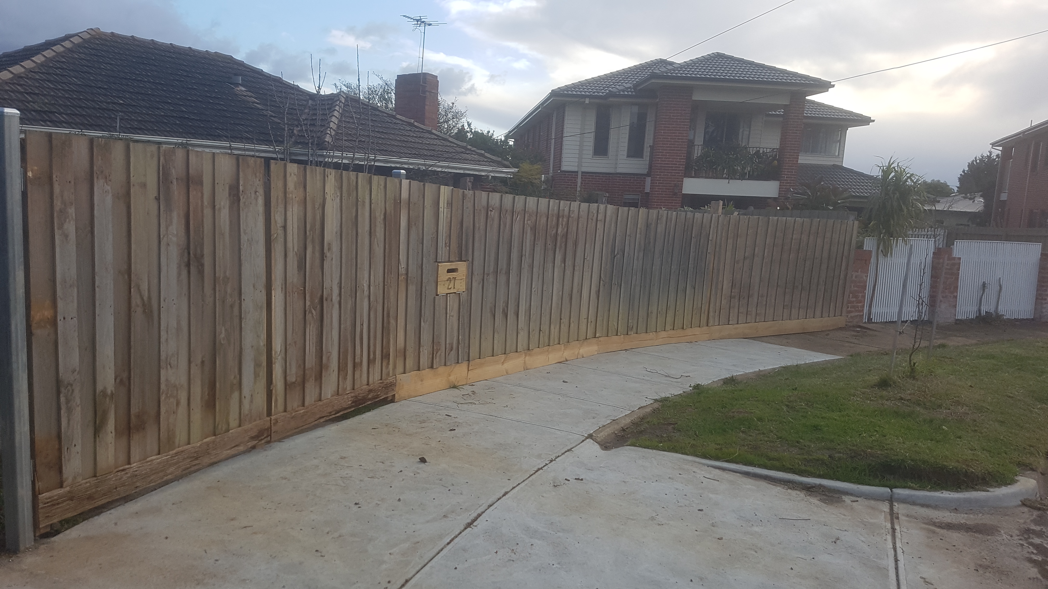
I had previously been given a whole treated pine paling fence (about 15 meters) from a nearby demolition which was in relatively good shape and only about 3 years old… this had been sitting in my front yard for some time in 2.5 meter sections as it was a relatively boring job that I had no enthusiasm for. Now that time was no longer an excuse I decided to order a few steel gate posts, some bags of cement, and pick the best of the recycled fence posts. The whole thing was up in less than a day after the posts had set… which left me with the question of what to do for gates.
I built some very quick and slightly shoddy gates out of the out of the old rails and palings, which were OK, but manually opening and closing them was generally dissatisfying. I could have fitted electric actuators, but even the cheapest and shoddiest ones are quite expensive, and the thought of little brushed motors and nylon gears sitting out in the baking sun and having huge stresses from strong winds put on them concerned me. So after almost tripping over my front water tap for the 15th time while fitting the new letter box, I had a moment of inspiration… why not use the mains town water pressure to power hydraulic actuators. Initially I was going to make them out of PVC pipe, but I found a 2″ galvanized fence post in my metal rack and I already had a whole tub of galvanized pipe fittings… so there was really no other choice.
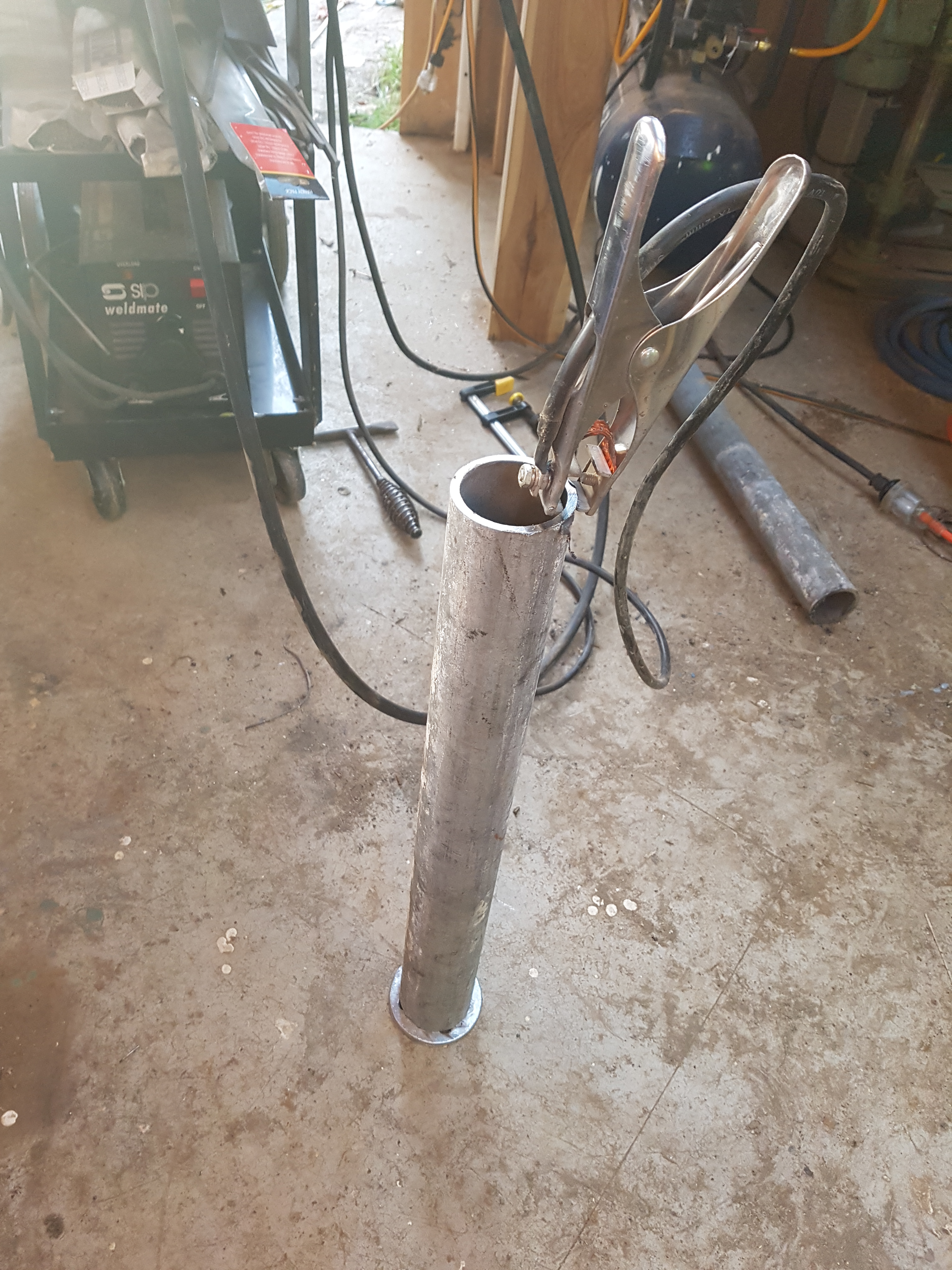
I decided on a length of pipe that would give me plenty of wiggle room in terms of geometry and throw, and proceeded to grind as much galvanizing away from the weld contact area as possible without removing too much galvanizing in areas where we wanted it.
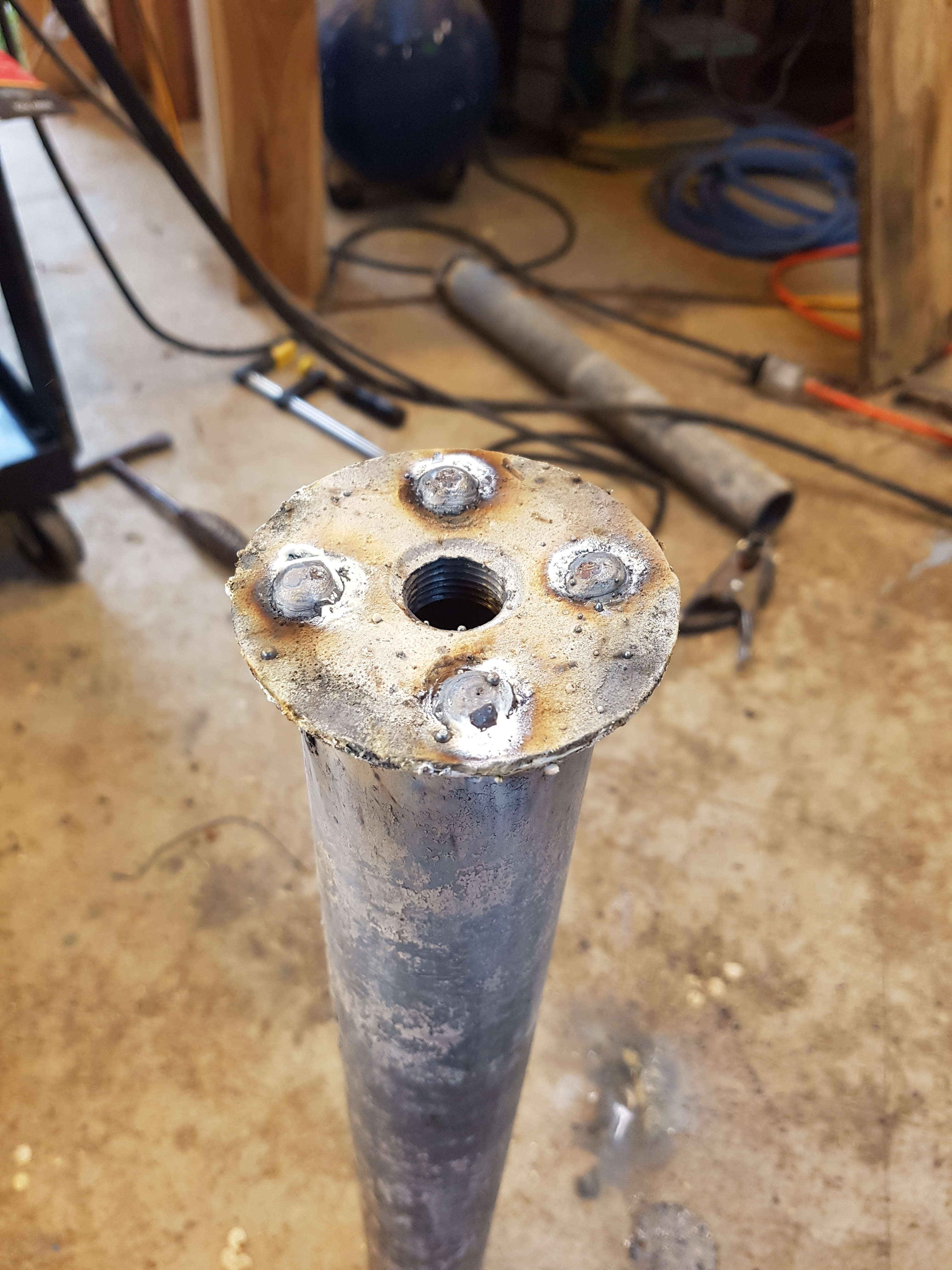
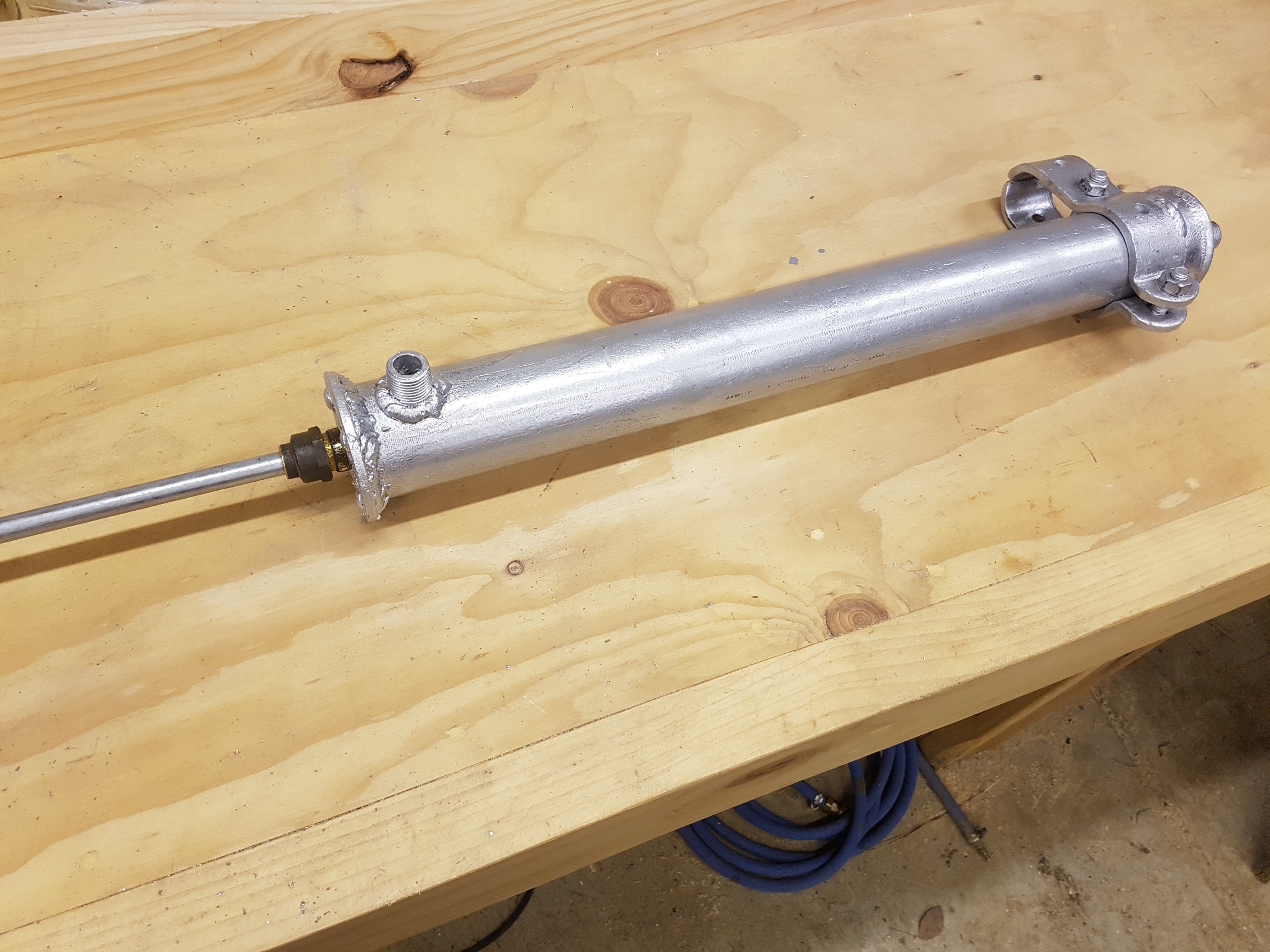
I then MIG welded some 1″ pipe flanges to the ends of the pipe trying to make it as waterproof as possible.
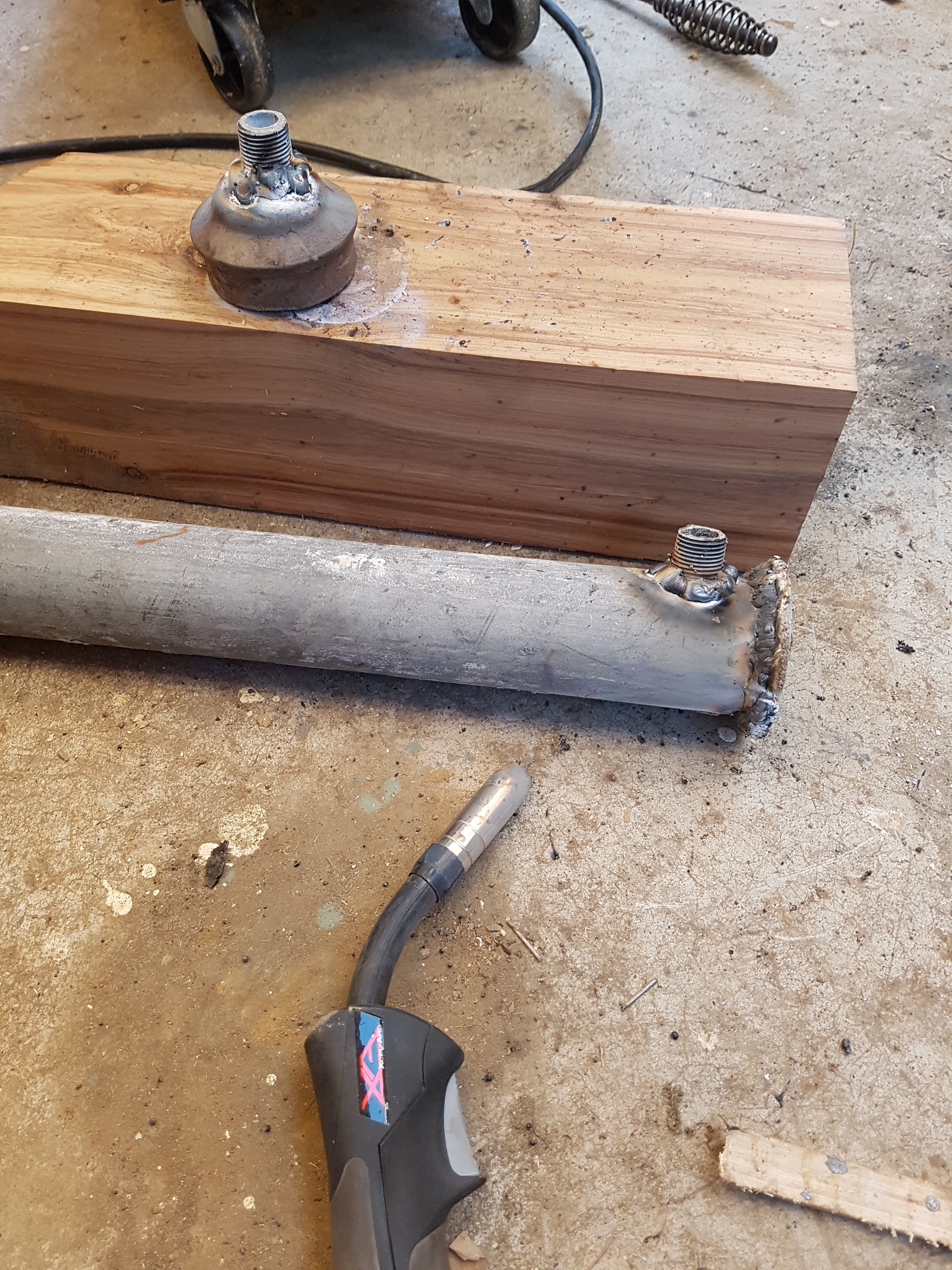
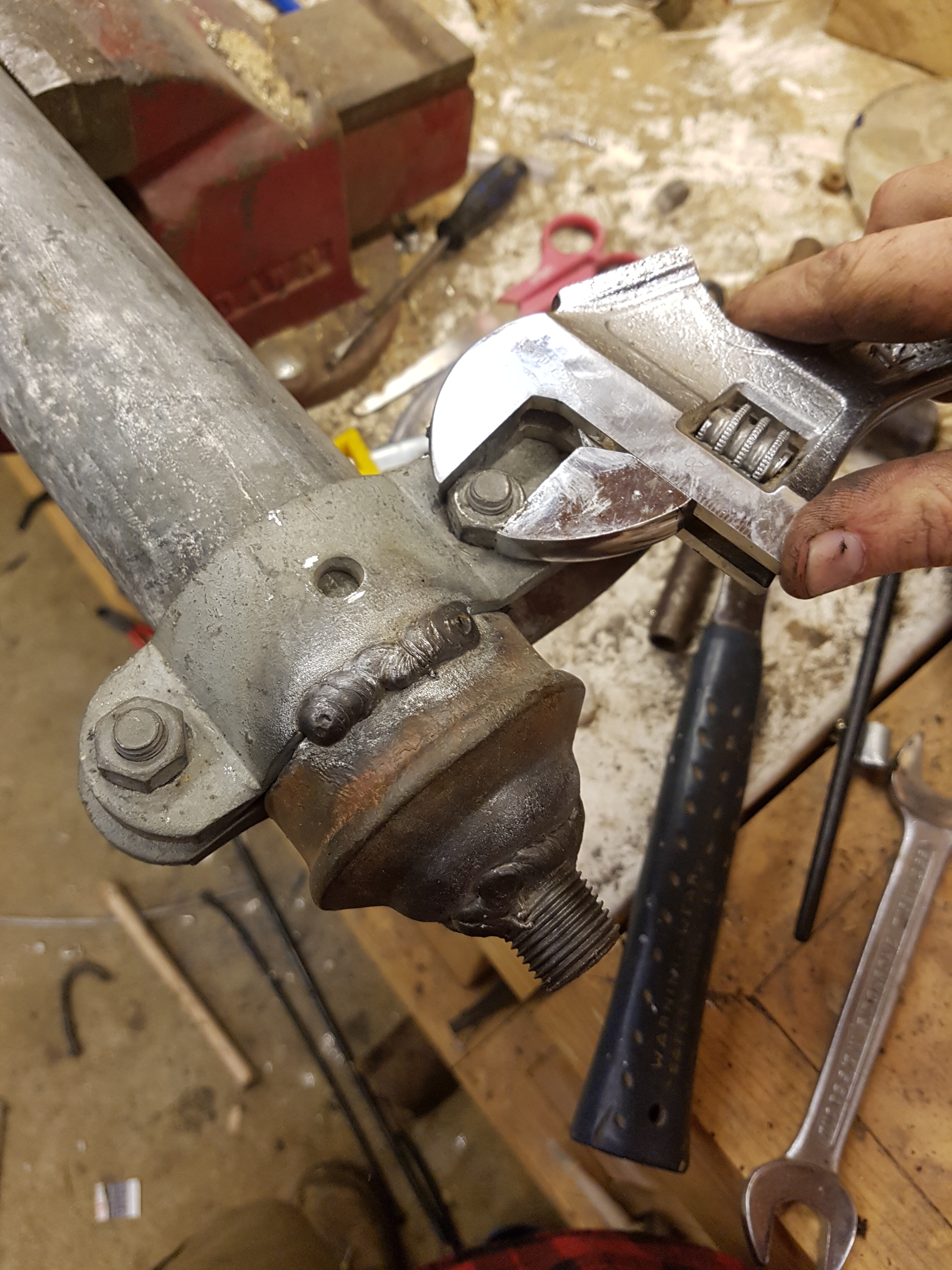
This was followed by some more badly welded 1″ male threads being added to the inlet/outlet holes at the end of the pipe. I must admit that the galvanizing contamination made the welding more splattery and ugly that I was expecting.
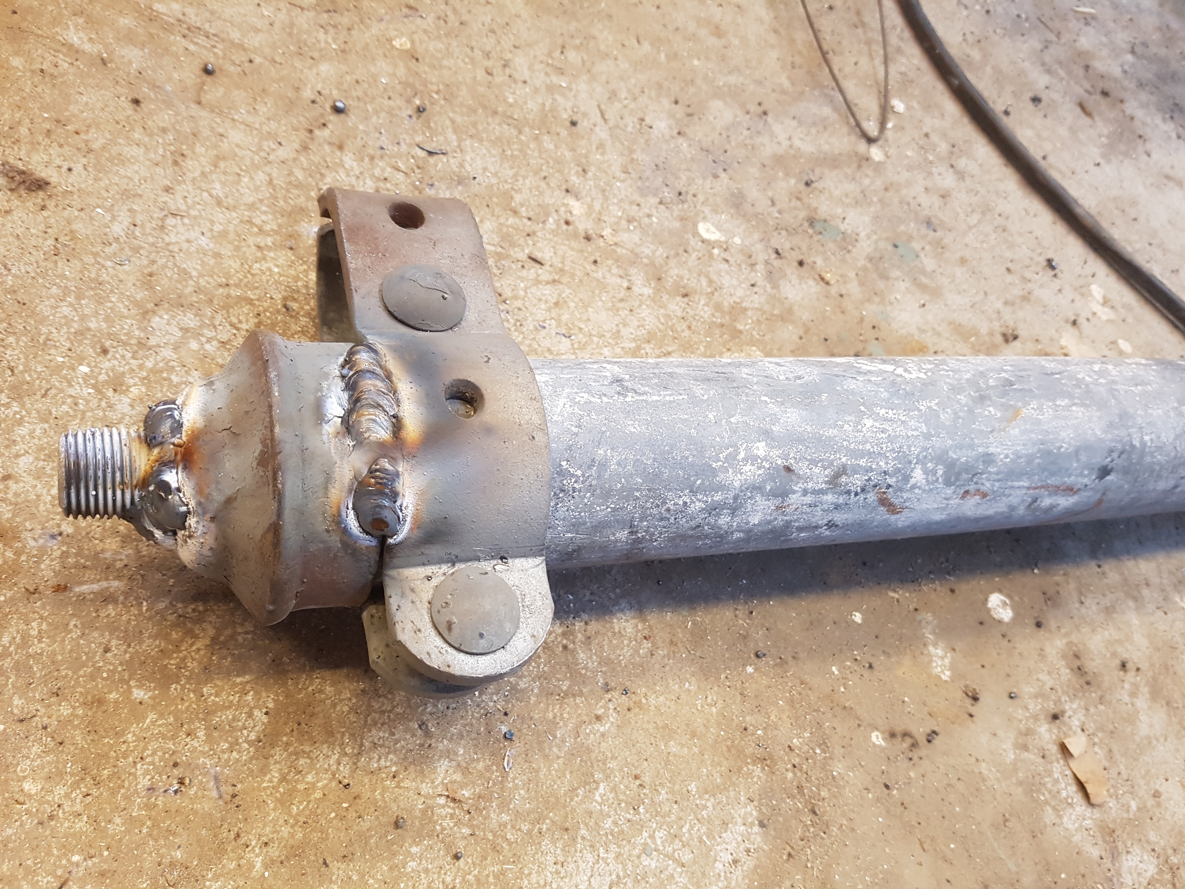
For the back of the pipe I used some more scrap fence fitting, pairing a hing bracket with an end cap… this allowed me to use the hinge brackets to tighten the cap onto the pipe with the two bolts, while also using the hinge brackets to pivot the whole ram assembly from the gatepost.
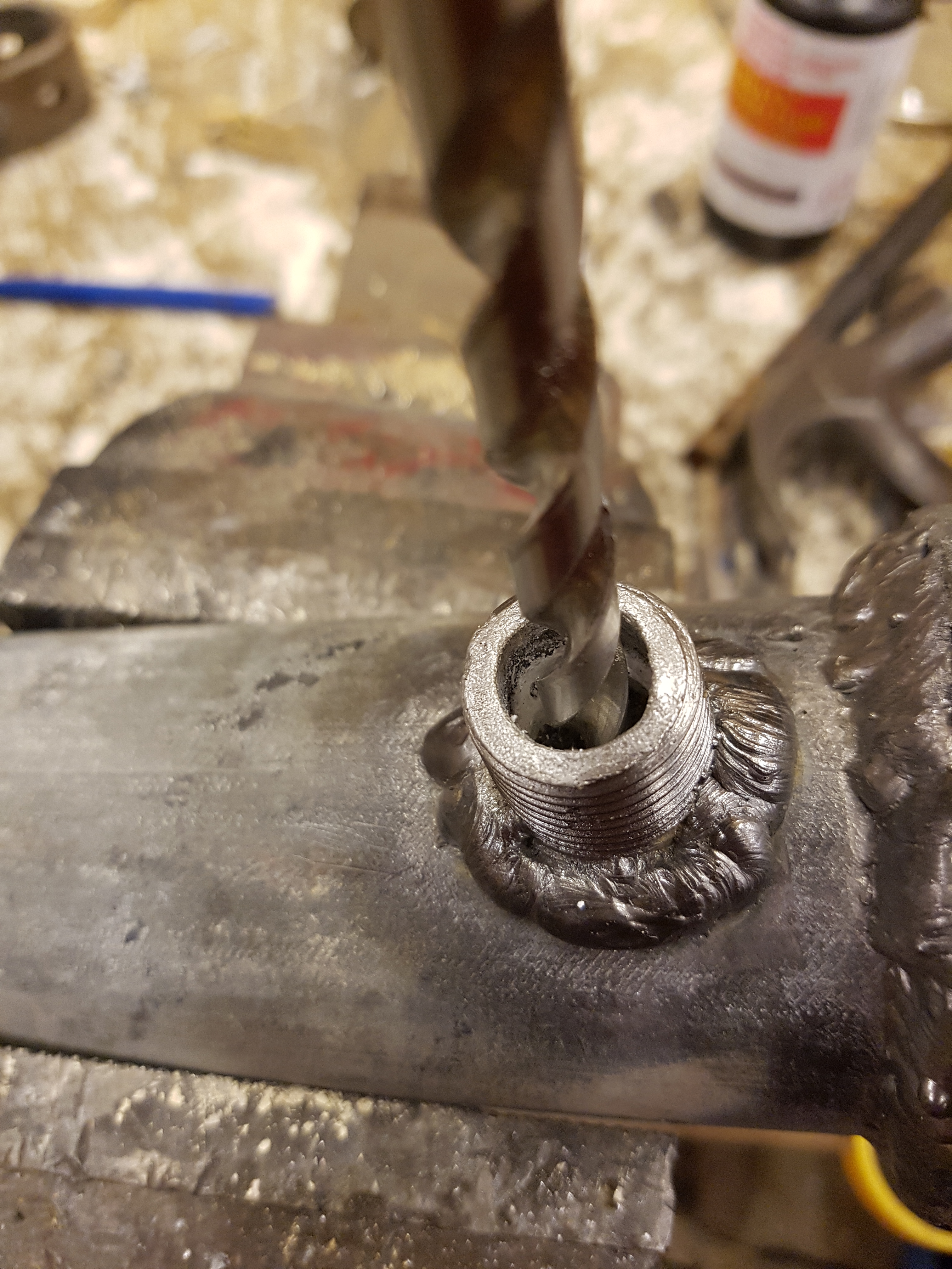
I then drilled out all of the inlet holes, it’s a tedious detail, but if I don’t add it, someone will mention it.
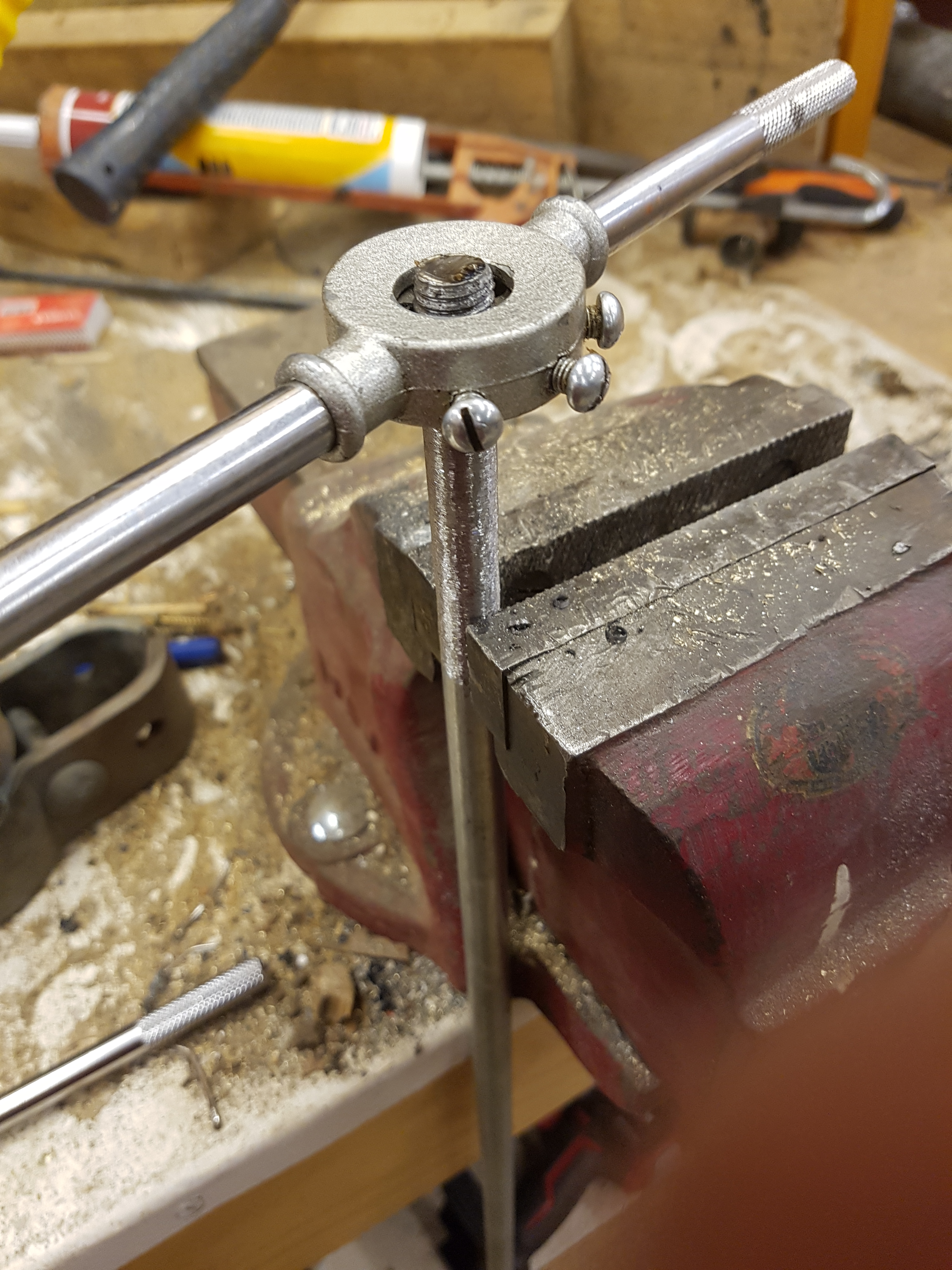
The next part was making the plunger, shaft and seal… this was surprisingly easy, but getting the seal just right required a bit of experimentation. I started by cutting a length of 12mm rod, grinding the galvanizing off the end section and running an M12 die down it.
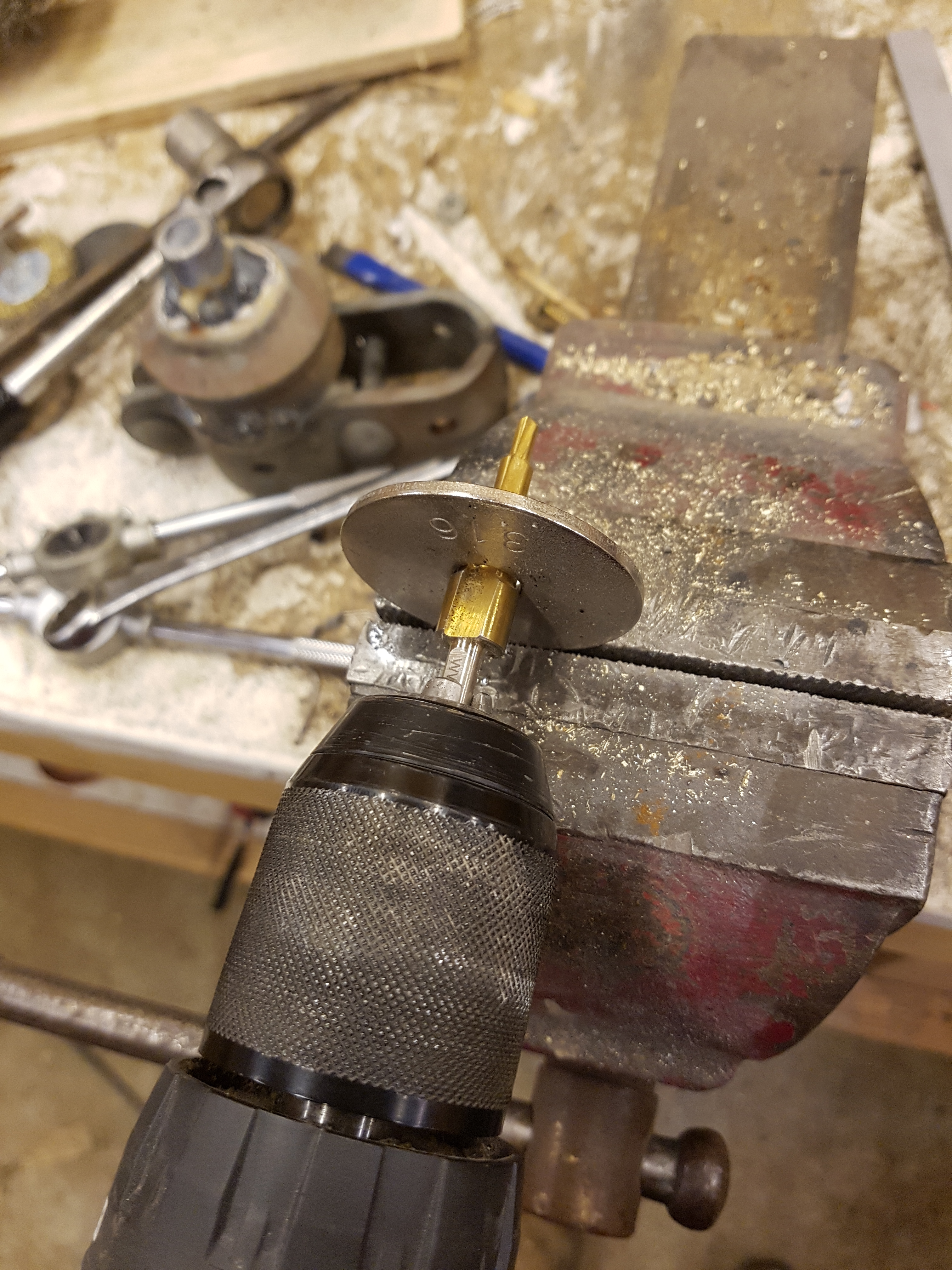
I then reamed out some large stainless steel washers and added some galvanized lock nuts to the shaft.
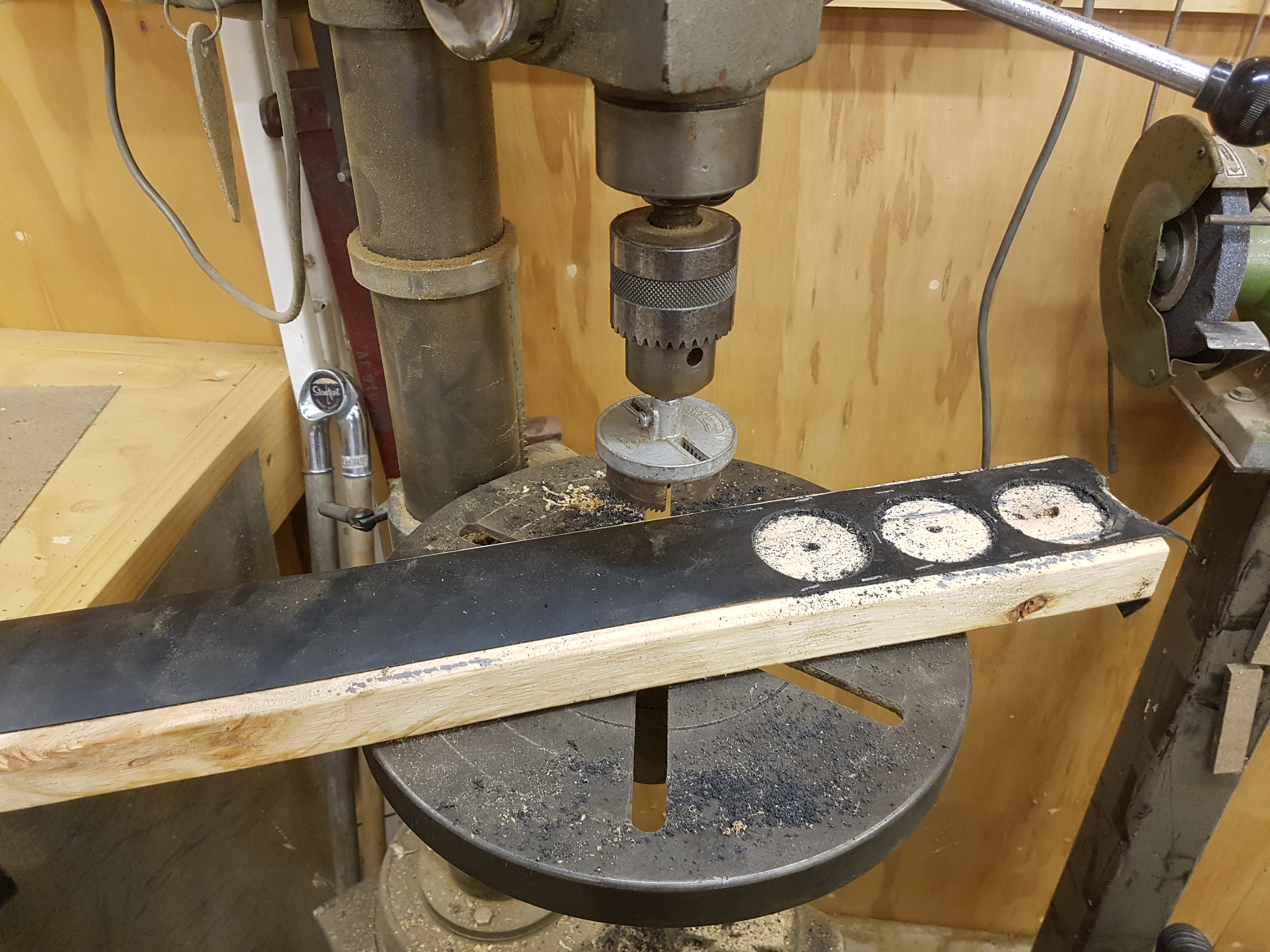
I cut some rubber discs using a hole saw, that was freakishly the right size for the inside diameter of the pipe… who would have thought.
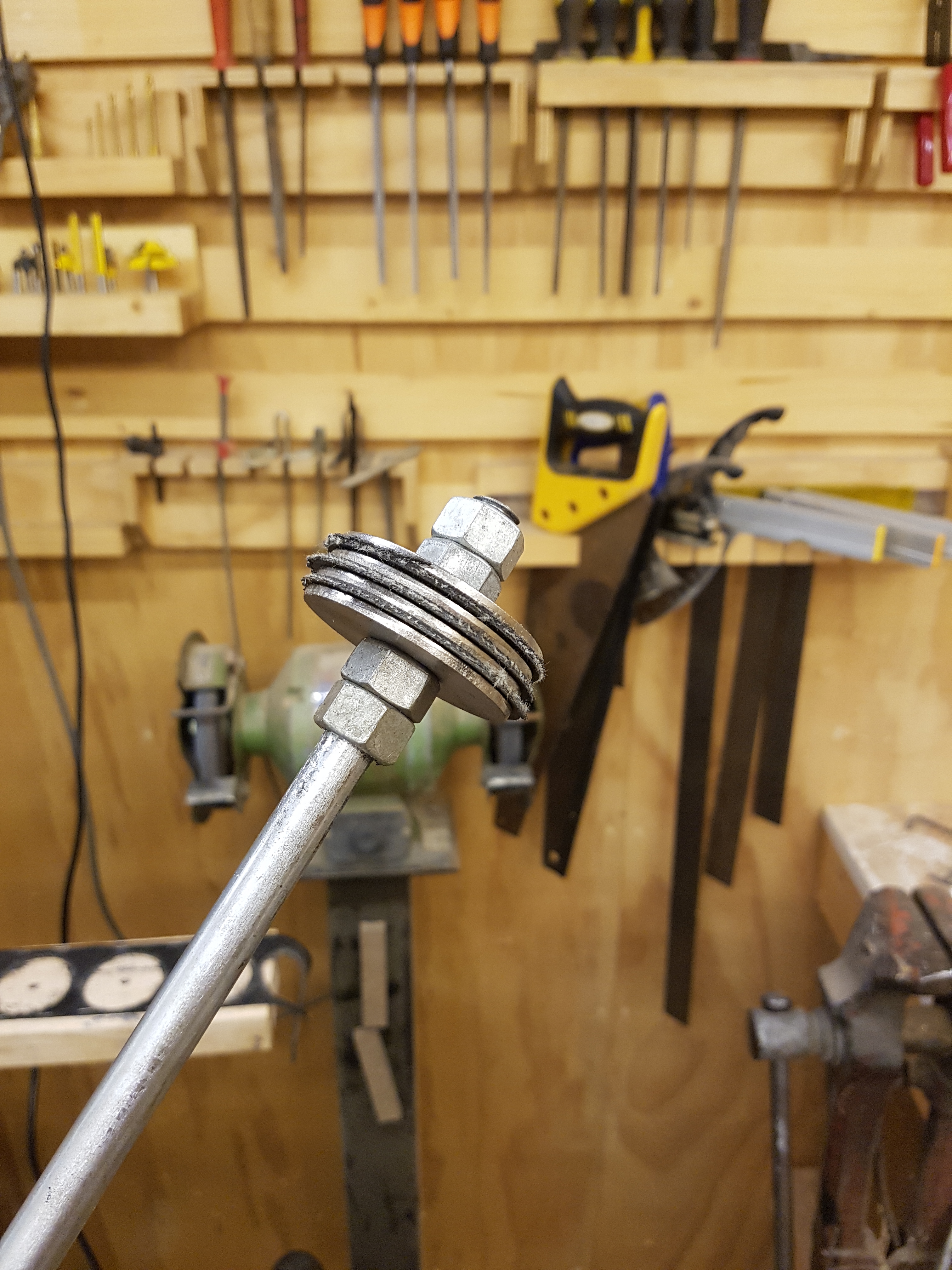
The initial seal was a sandwiched between a stack of washer with lock nuts either end, but this proved not to be very durable.
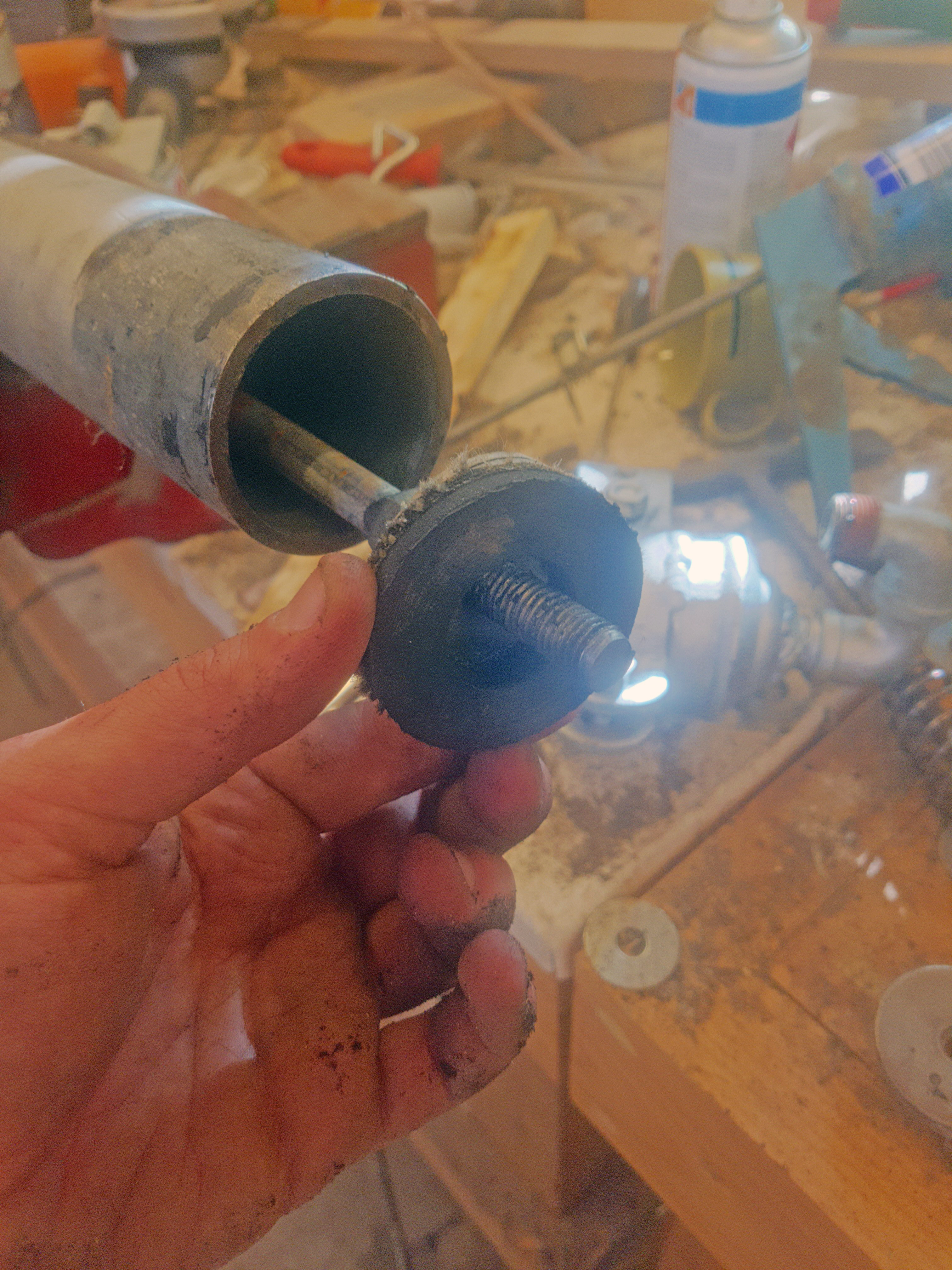
So after some scrounging I found a piece of really thick rubber with internal webbing… which I gave the same hole saw treatment to… but I also cut a smaller hole through the center… the idea for this is that it gives the seal some inward/outward pretension and flexibility. I then sandwiched this between two washers either side and tightened it down till it made a good but free seal with the pipe wall using lock nuts. Be sure to use grease, and tighten the nuts once the seal is already inside the shaft… or you will never get it in. Also be sure that the plunger and seal run smoothly along the full length of the tube without the washers touching the pipe wall.
Running a cylinder hone down the pipe made sure to grind away any of the galvanizing dags… after all galvanizing is not an exact science and can leave a rough surface.
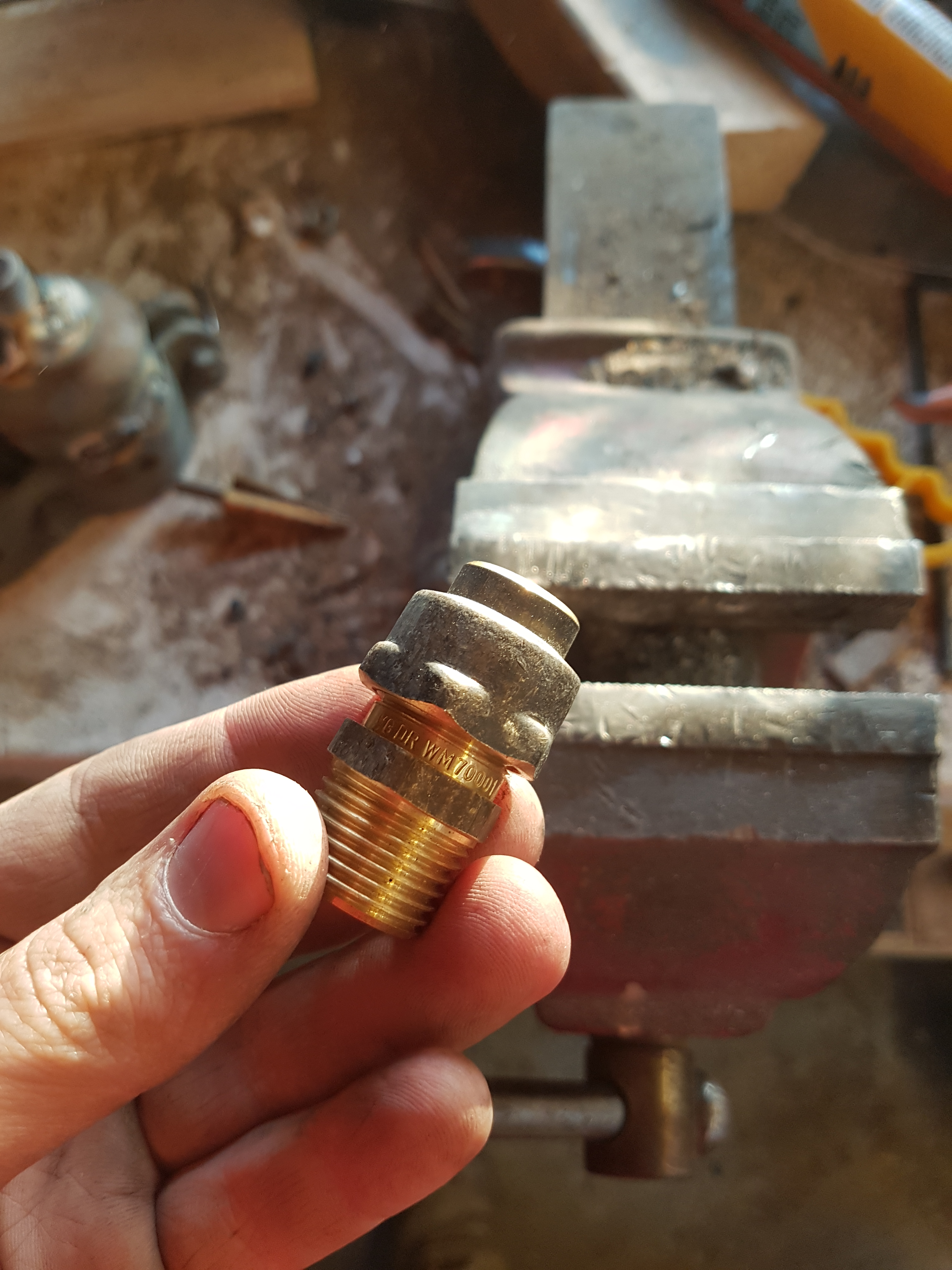
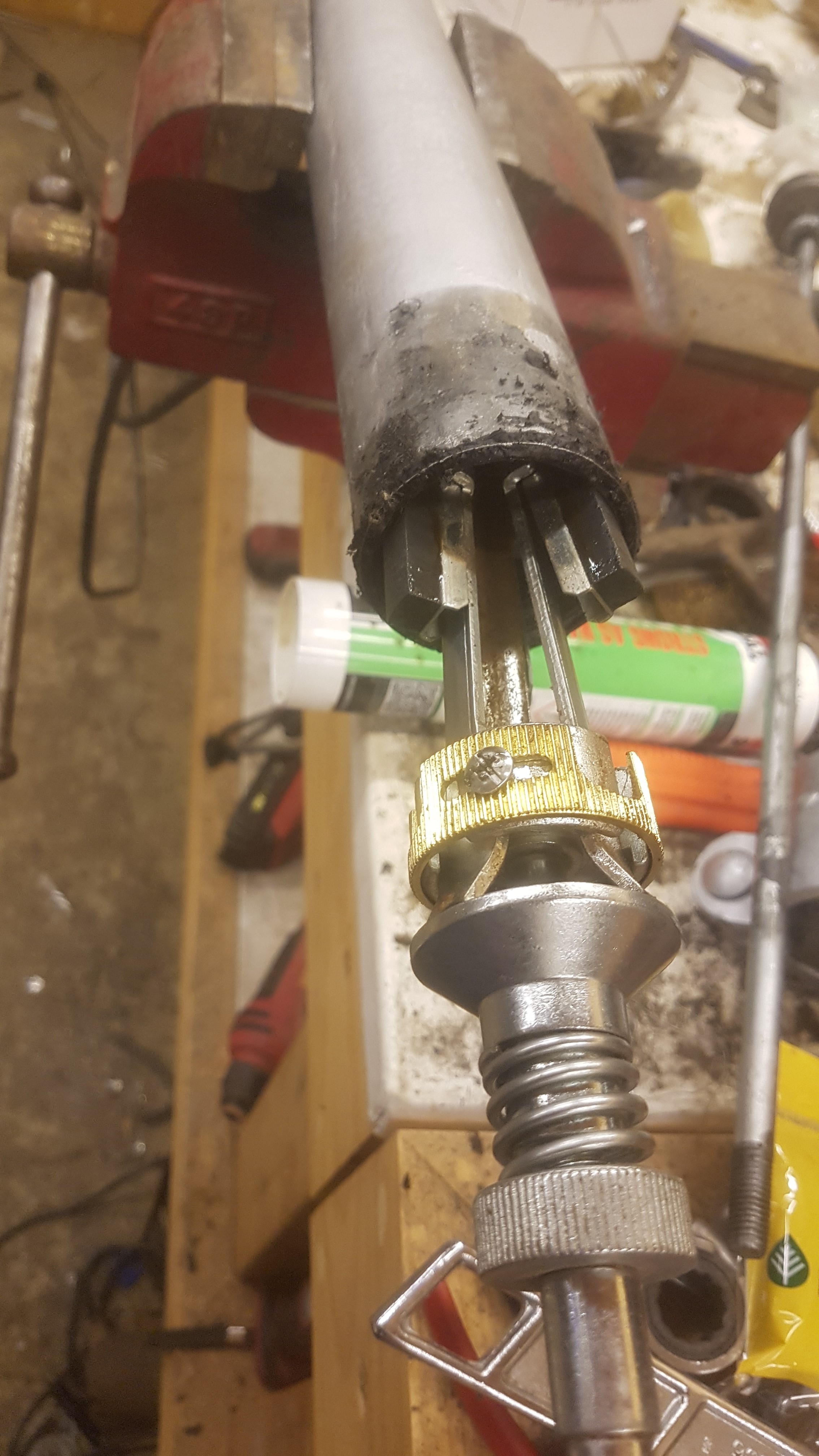
The end seal is made from a standard brass compression fitting with a slight modification.
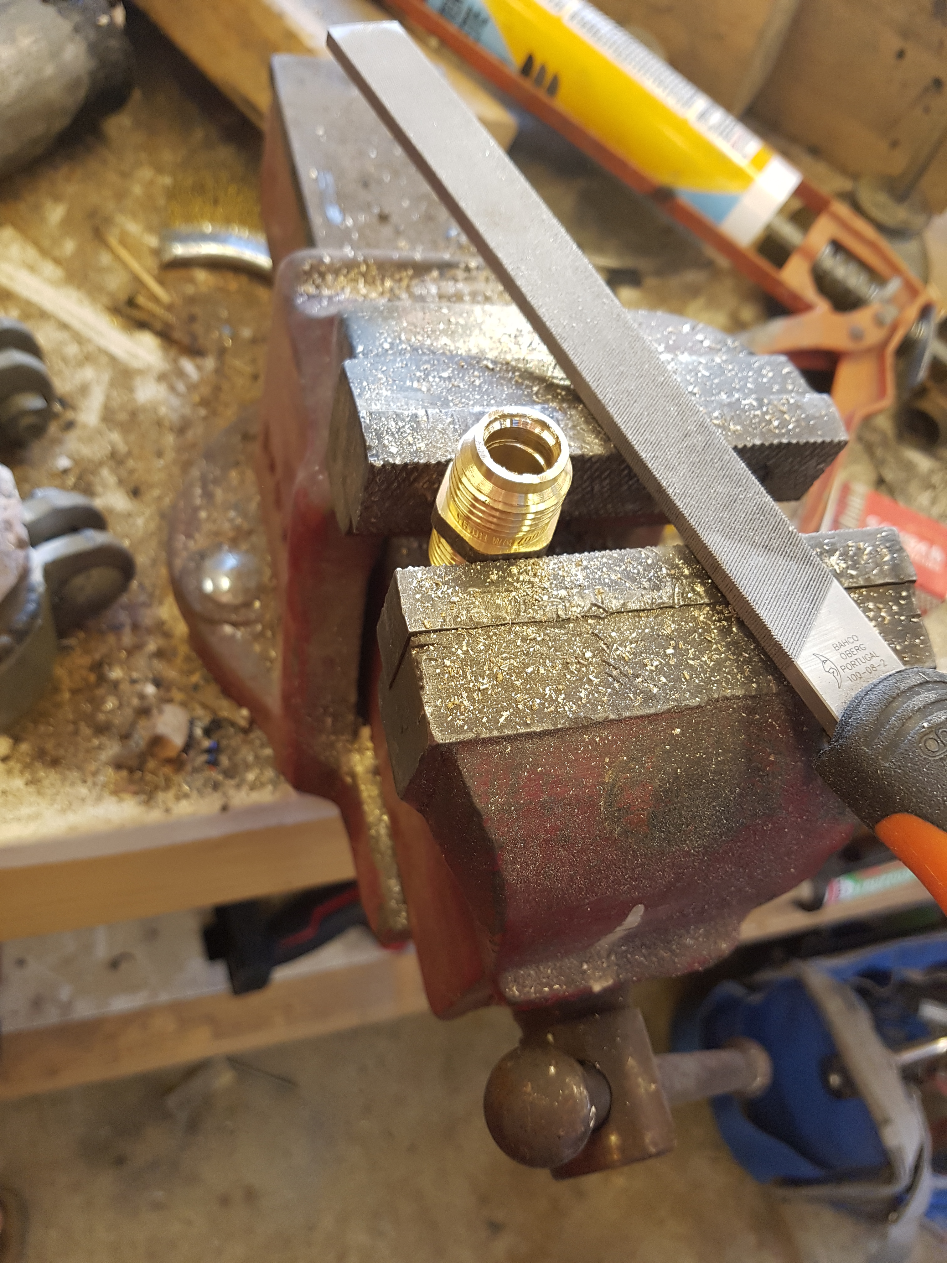
The center is drilled out with a reaming tool and the end ground as flat as possible.
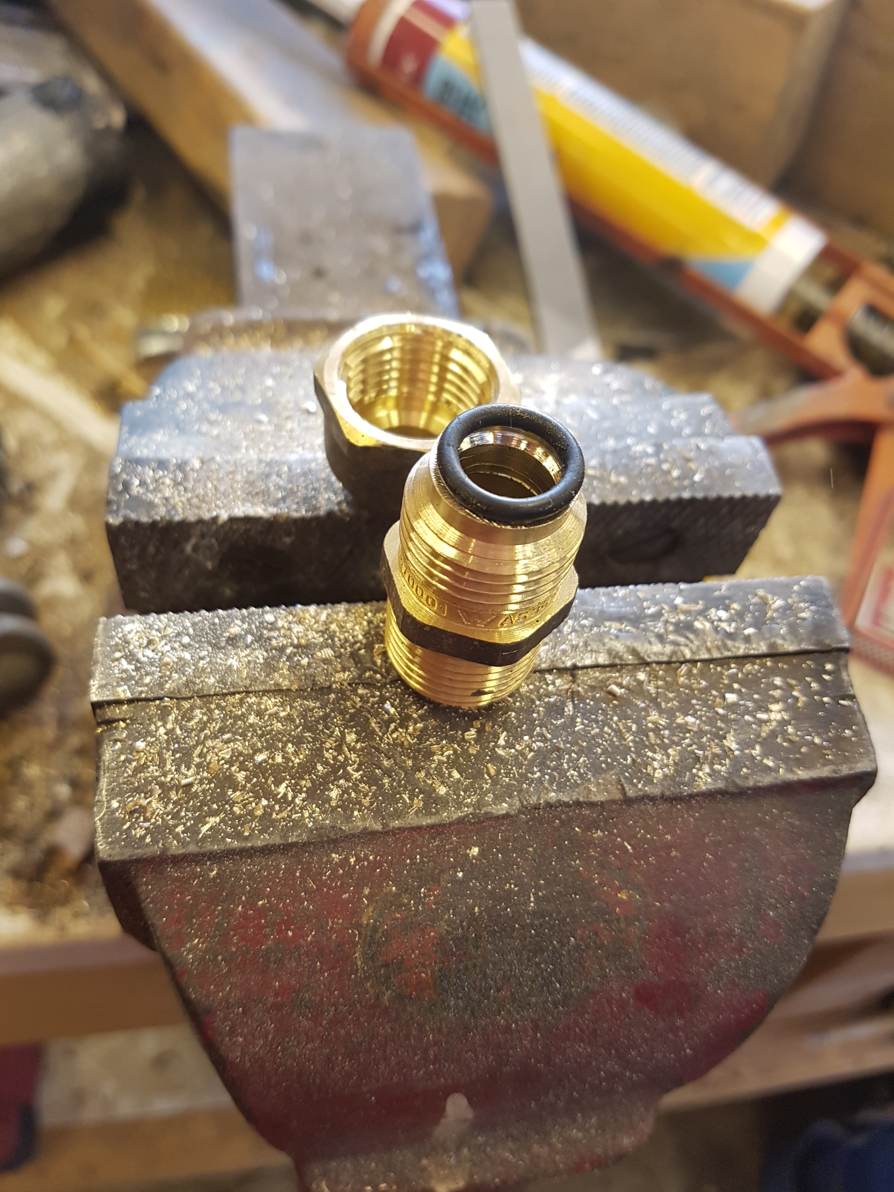
This allows us to fit an O-ring under the compression nut and use it to tension the O-ring onto the shaft until it seals nicely.
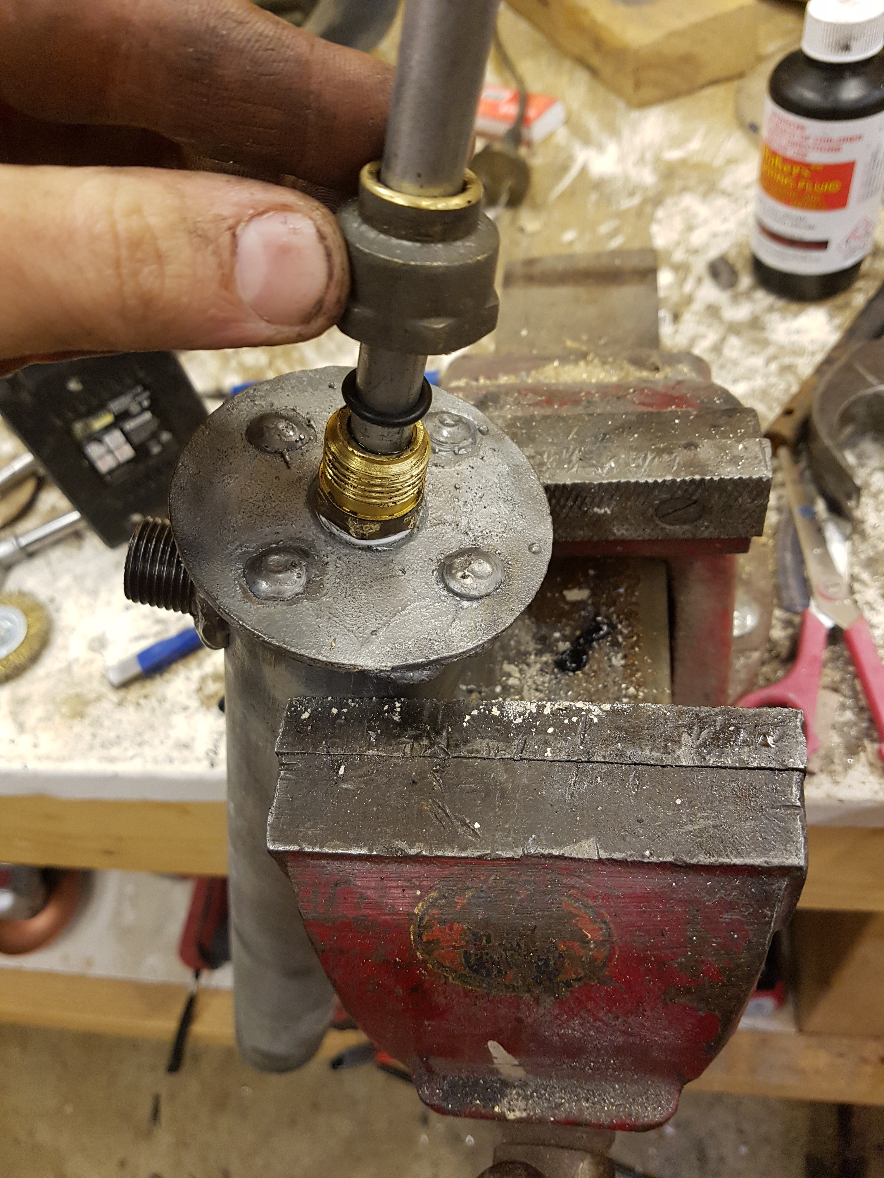
Some teflon thread tape to seal it into the end of the cylinder nicely, an O-ring under the compression nut and you’re good to go.
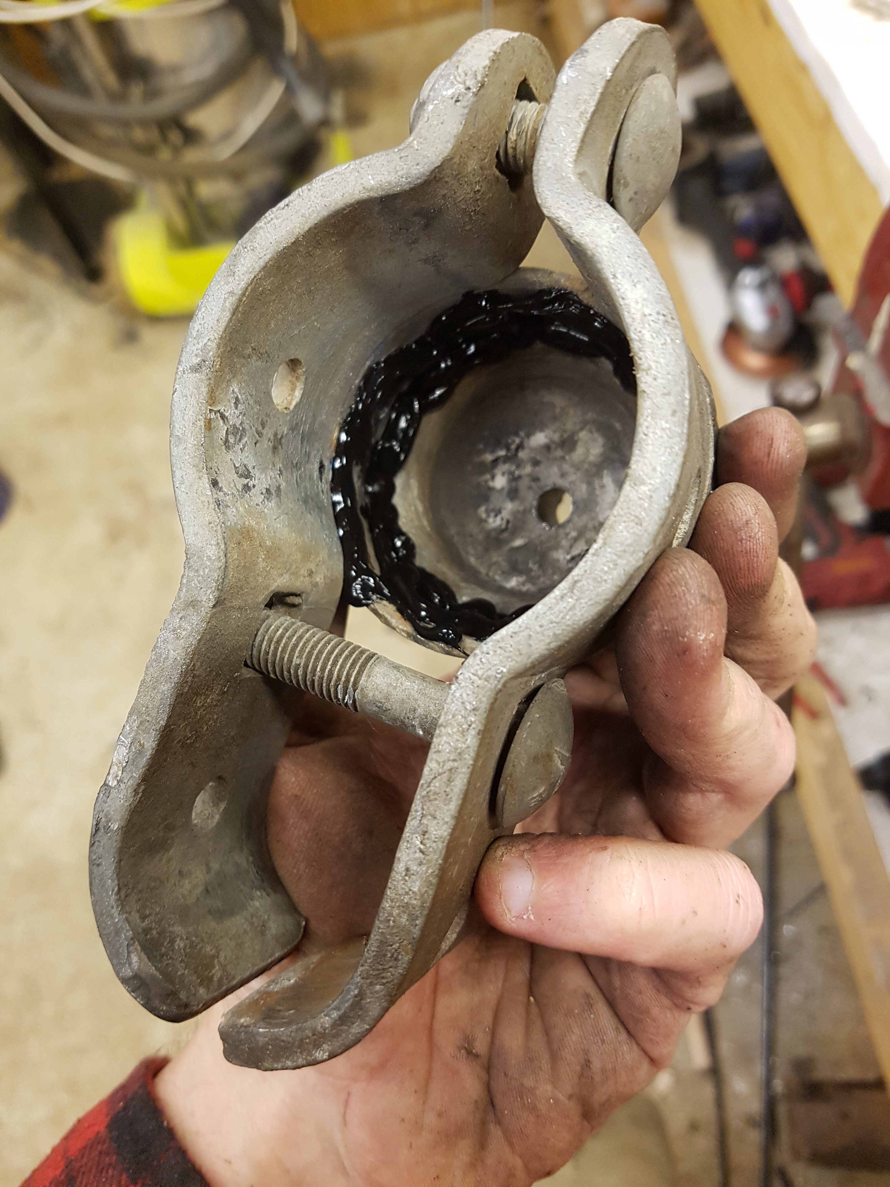
To fit the end cap add a generous bead of your preferred water resistant sealant.
Then tighten the nuts down to clamp the whole assembly together.
A lick of cold-gal paint and I think it comes up a treat… if not a little steampunk.
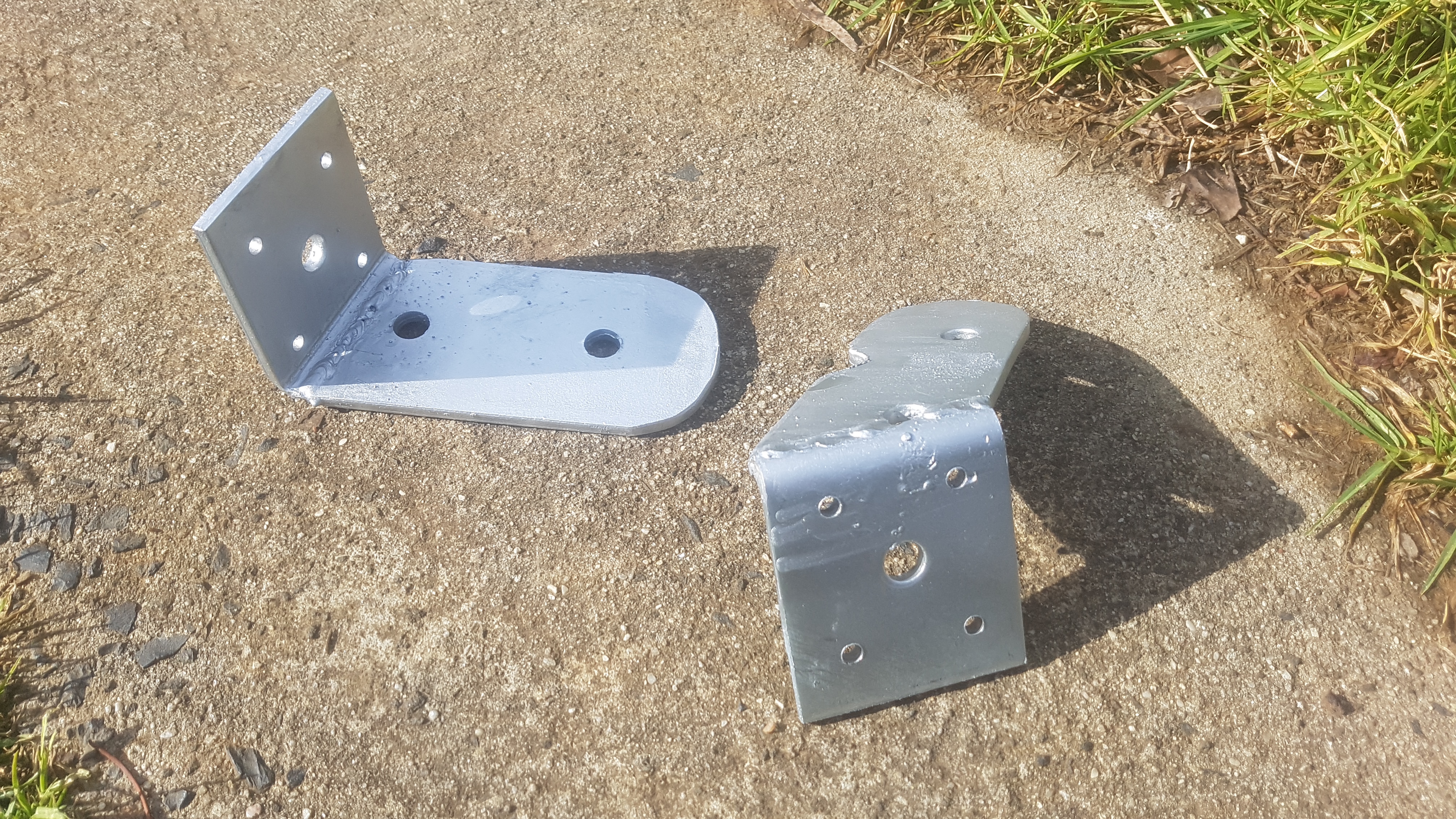
I welded up a few brackets with angles that seemed as if they would probably work, but there was really very little science going into anything at this point.
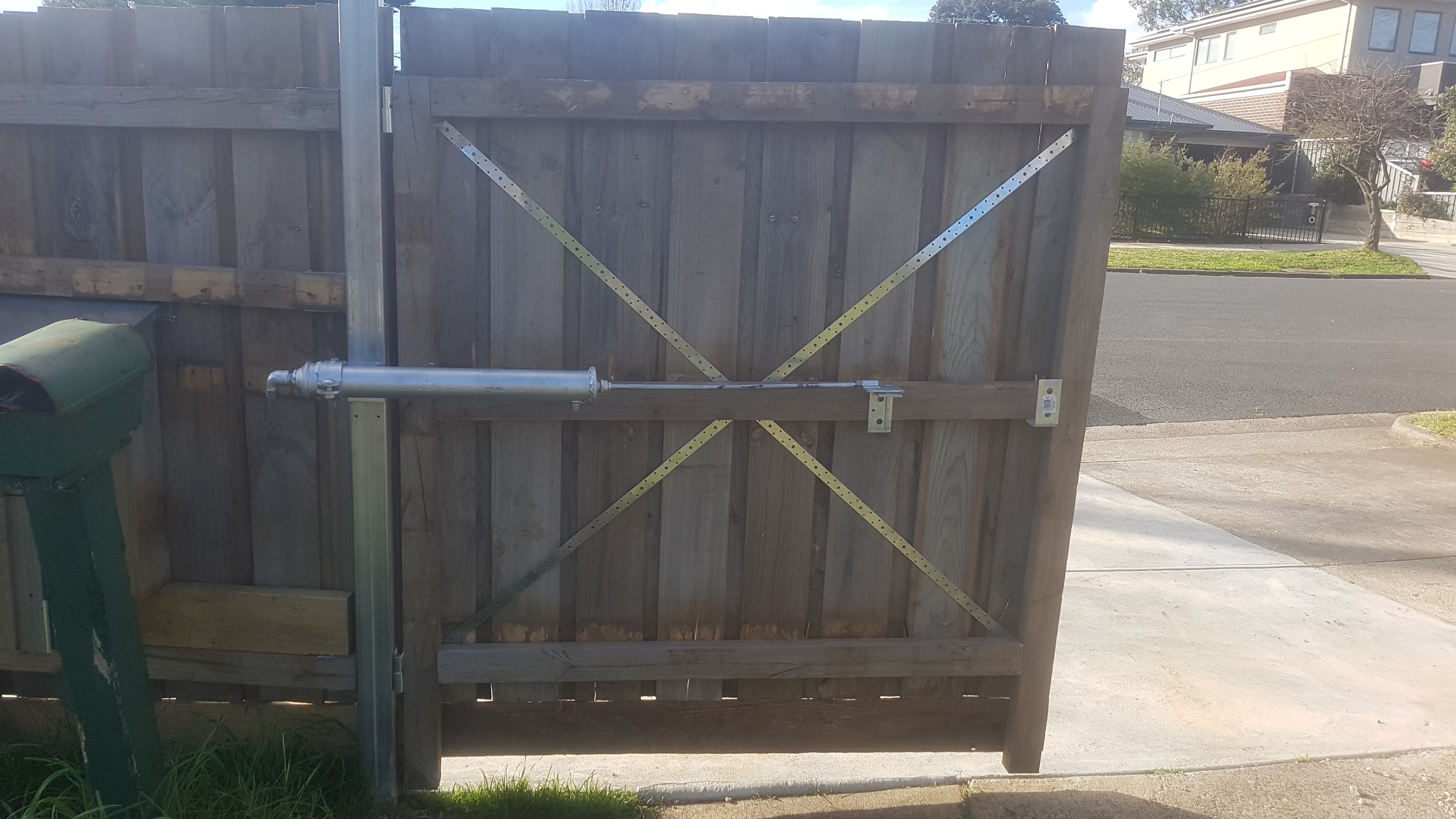
The brackets were screwed to the gate and post, and some holes were drilled to pivot the ram from.
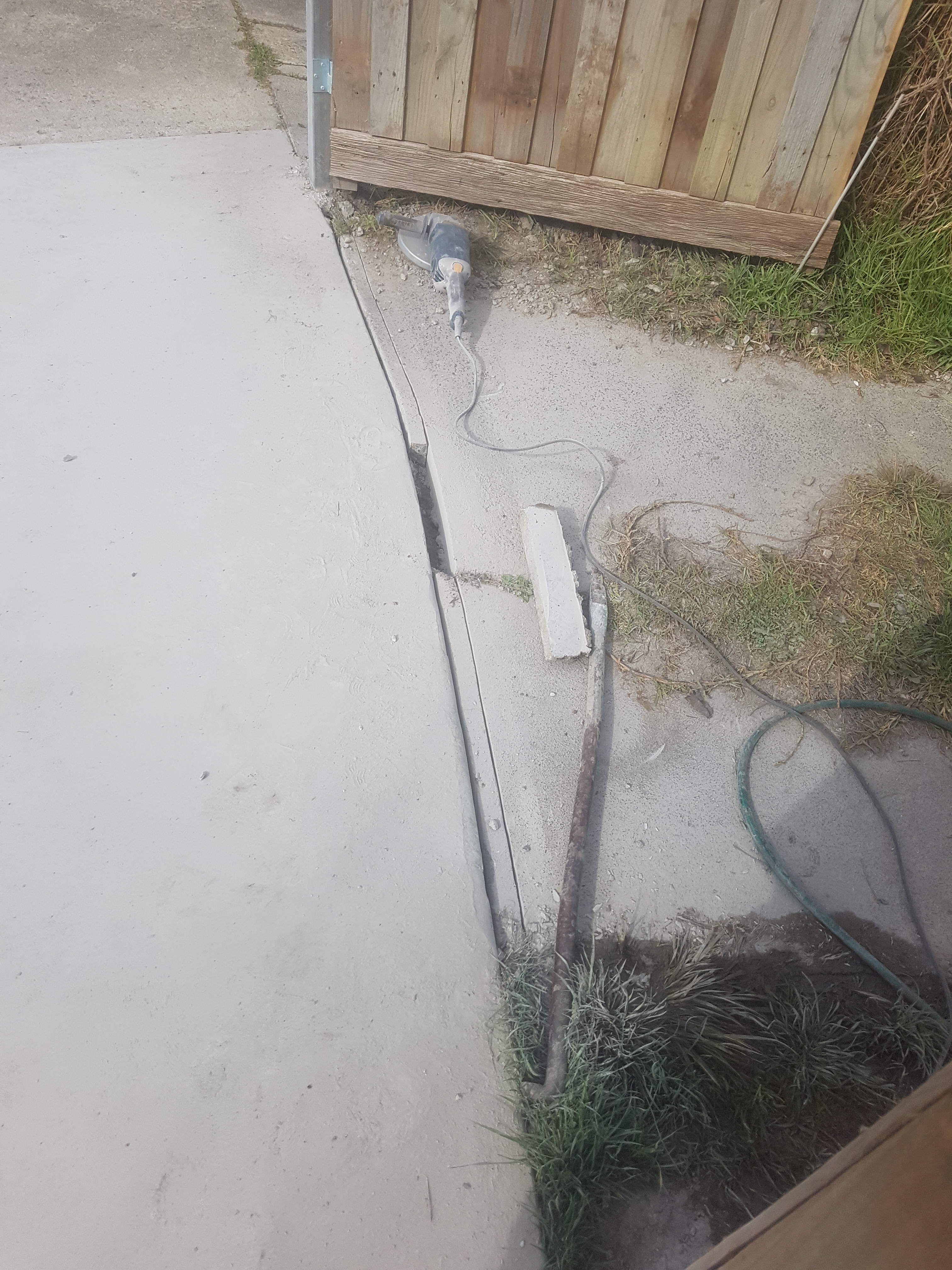
Out comes the grinder and crowbar.
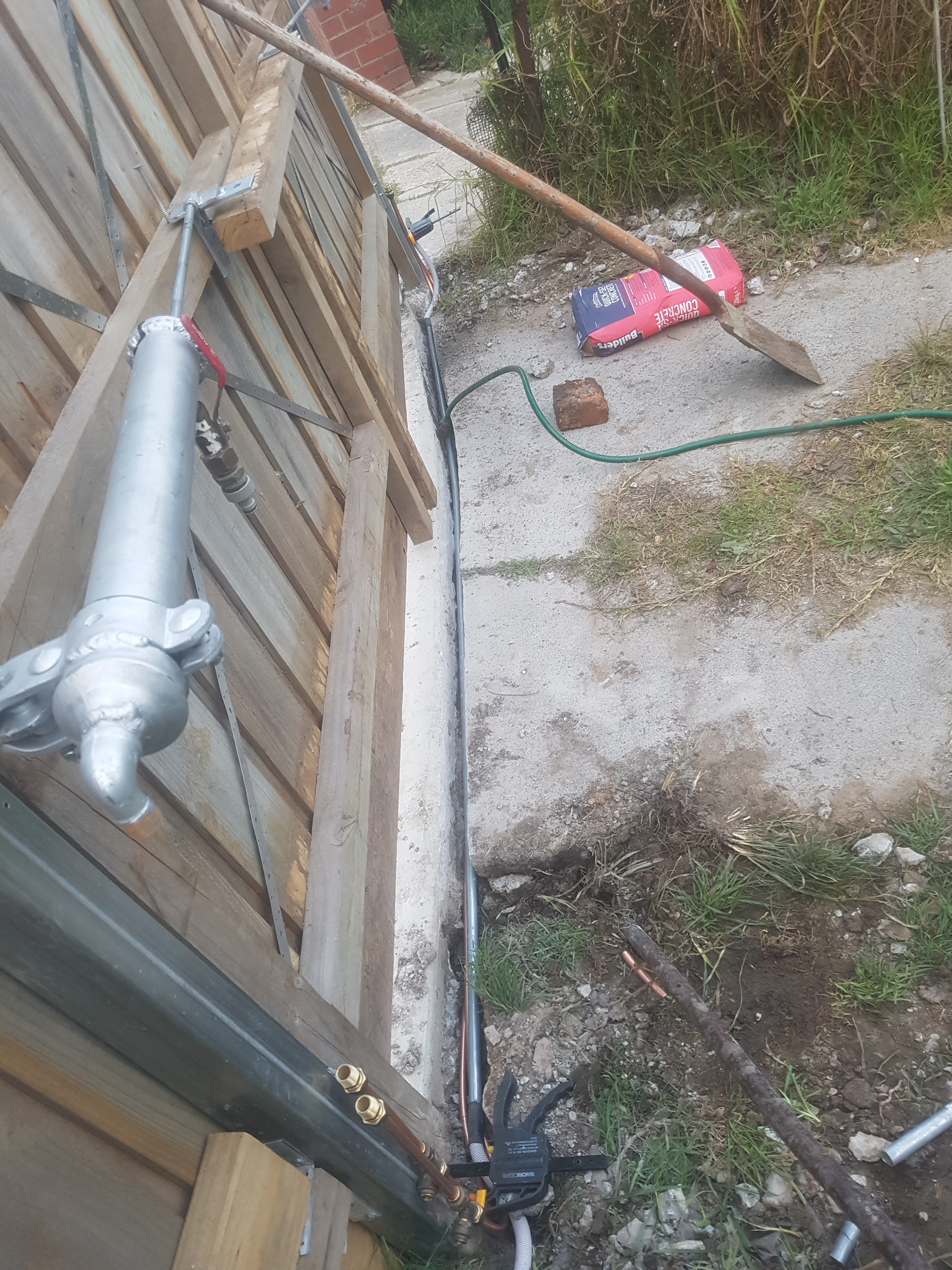
I cut a trench down my drive way to conceal 2 lengths of copper pipe and a length of galvanized conduit . Threaded compression ends are added to the copper as well as some T-pieces. The conduit was futureproofing myself in the even that I needed an electromagnetic lock… luckily the seals in these actuators are so good that it is actually impossible to open them, or even budge them with force.
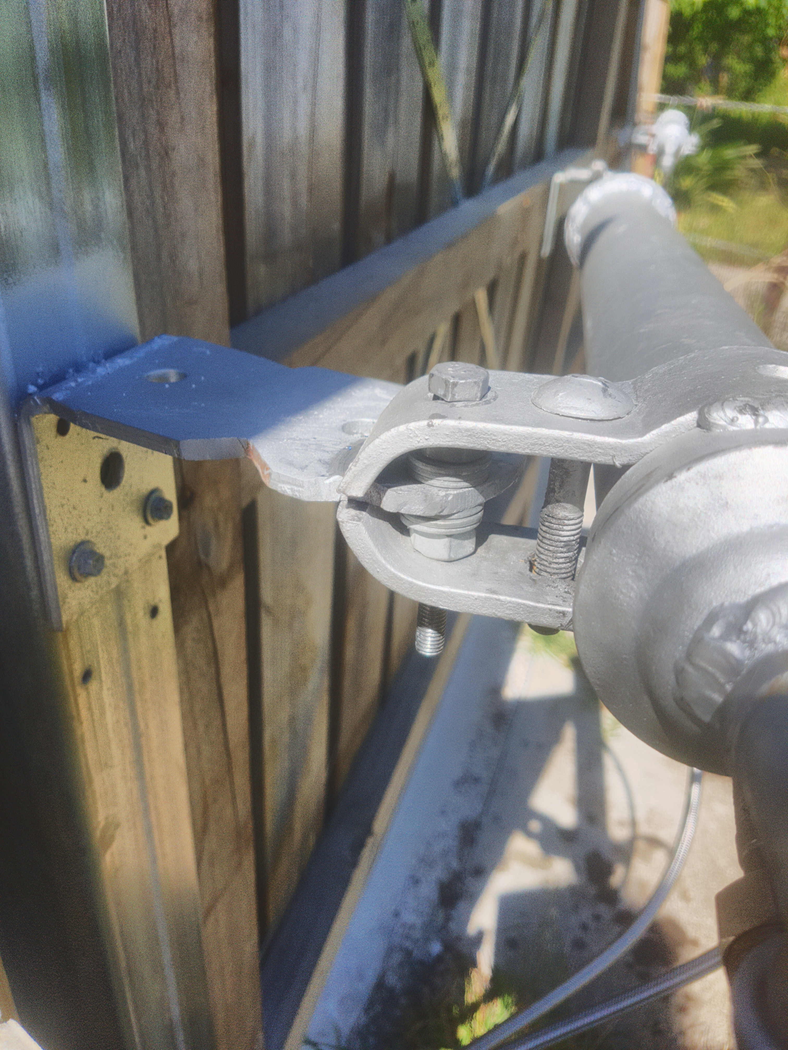
You can also see how the hydraulic ram mounts to the fence bracket using an M10 bolt with a few washers and nuts as spacers.
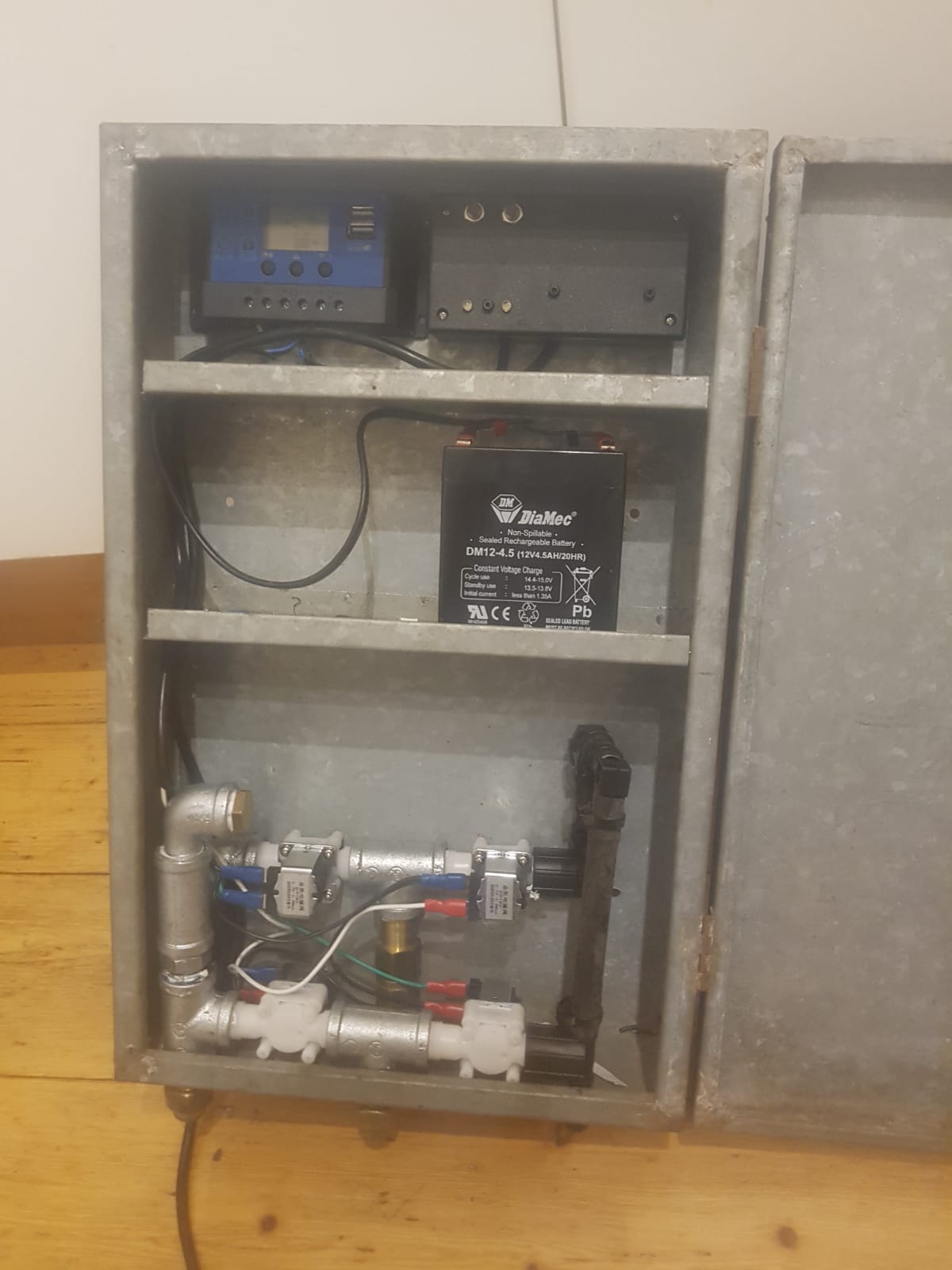
Now comes the control unit and circuit… I bought 4 cheap 12V solenoids from ebay, a 2-channel radio receiver module and scrounged some timer modules from my escape room spares. I had an old 12V SLA battery, solar charger and panel from an automatic chicken door project that never eventuated.
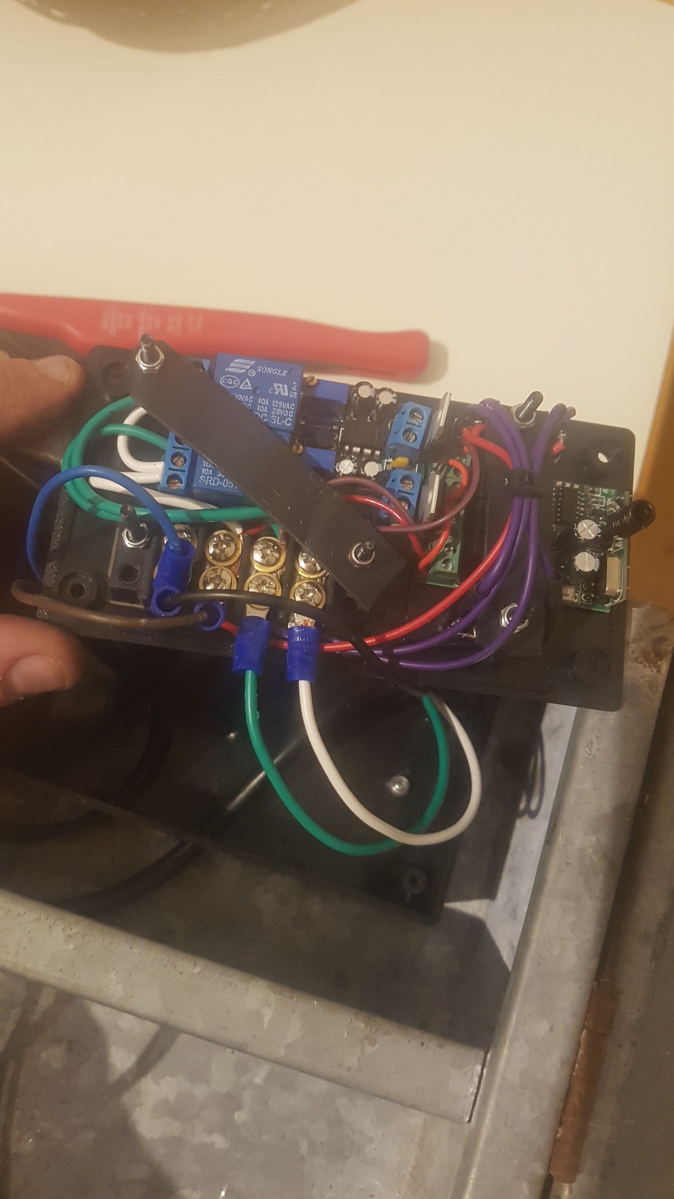
The circuit is super simple, in that when the remote is triggered, it activates the timer module which determines how long the solenoids stay on for when opening and closing the gate… the trick is to feed the 12 volts back into the supply of the timer so that it becomes self powering for the duration of that timer cycle… this allows the whole thing to be triggered by a momentary signal. In this case I have two 5 volt regulators powering my delay modules as I only had 5 volt ones on my shelf, anyone making one of these should just go straight for 12 volt timer modules. Obviously there is a timer module for opening and one for closing the gates, each one triggered by one of the two channel from the receiver. I also added two manual override buttons with indicator LEDs.
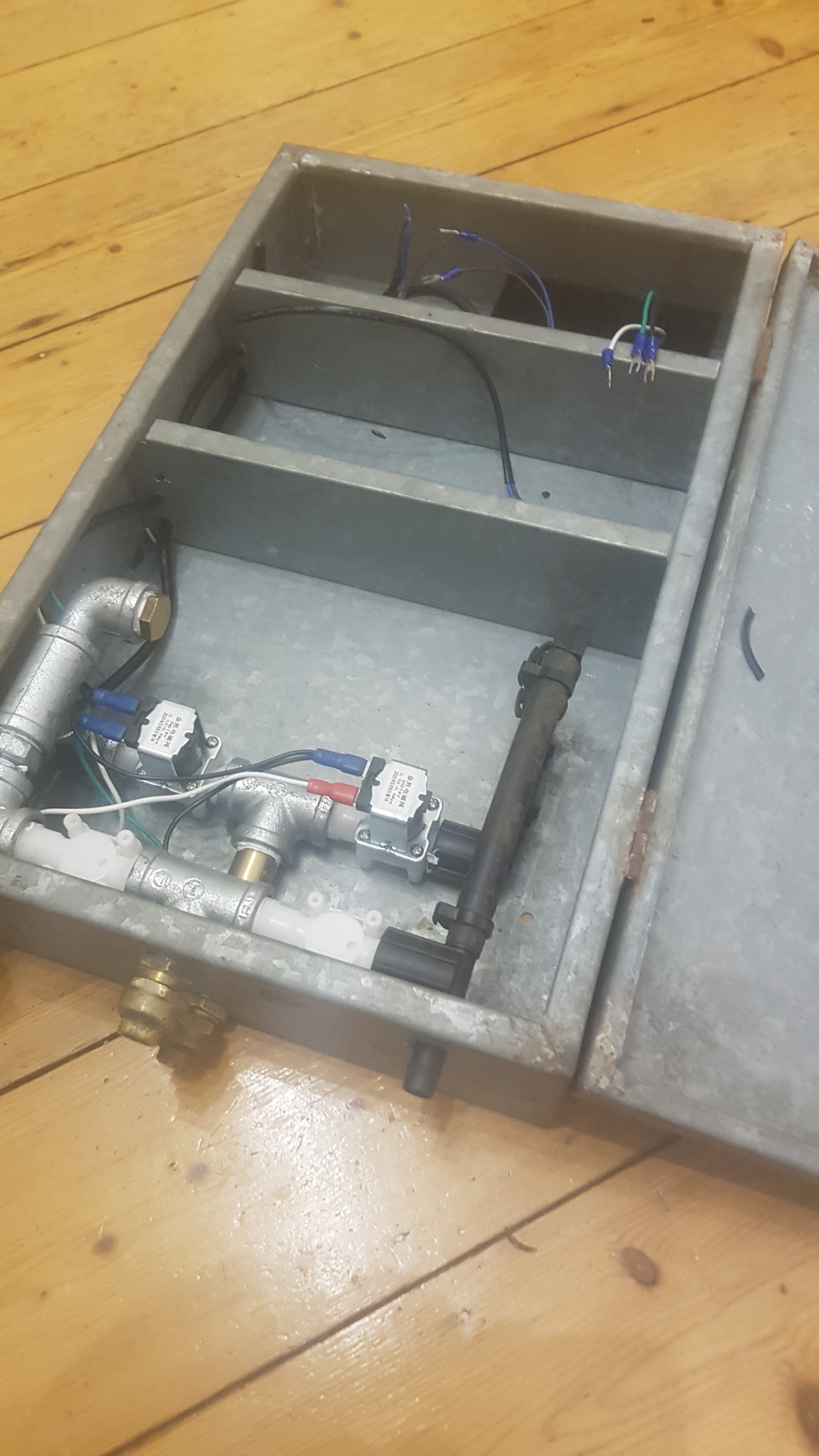
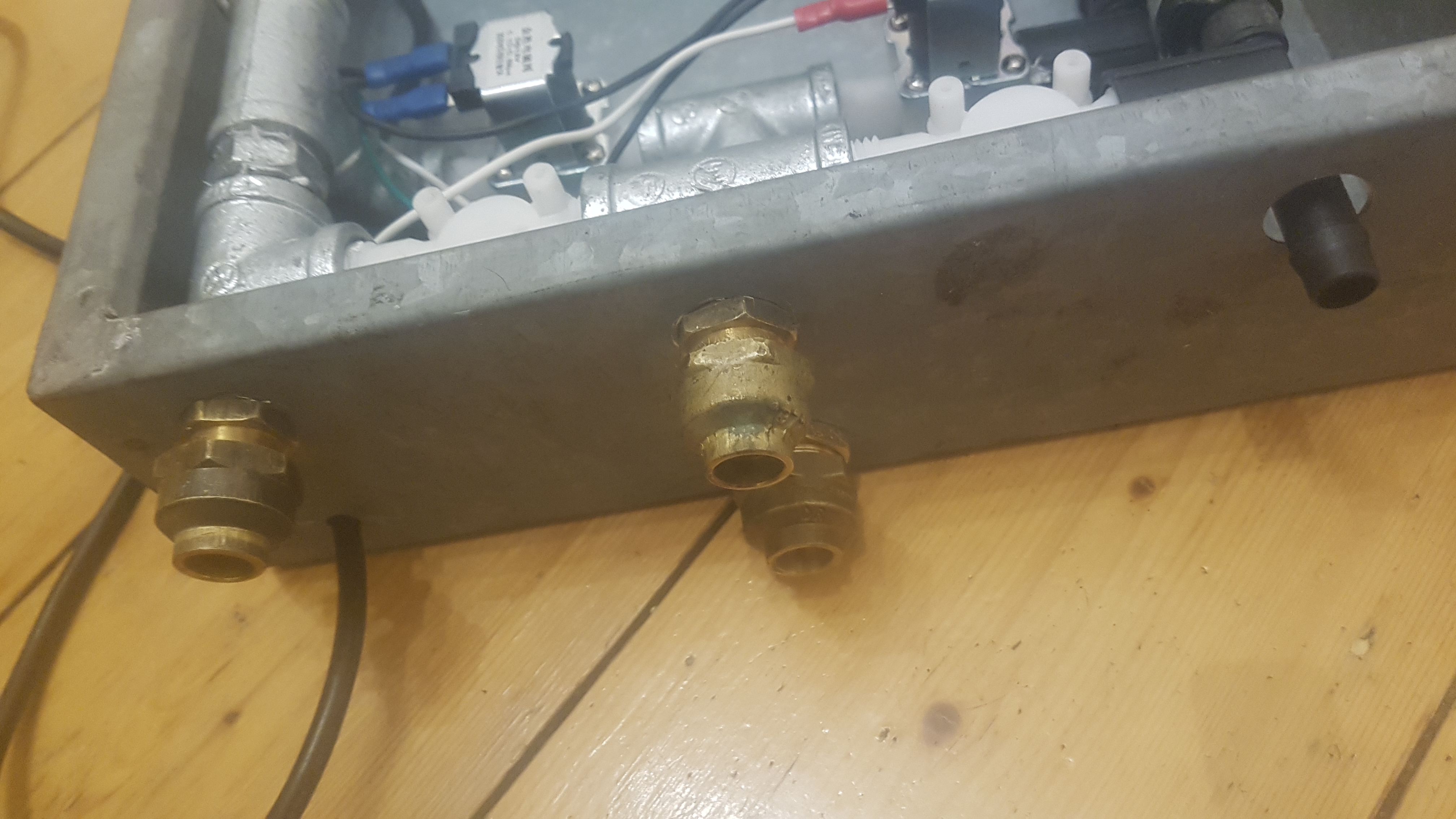
The solenoids are mounted in an old galvanized box that I found, you could really use anything waterproof. You can see how the solenoids are configured… the water comes into the housing from the left hand side and is split off into two solenoids… these solenoids in turn each run to a T-piece which terminates outside of the housing with compression fittings… this T-piece also continues to the second set of solenoids which flow to the waste water outlet which is done in 13mm black polly pipe and terminates outside of the housing too.
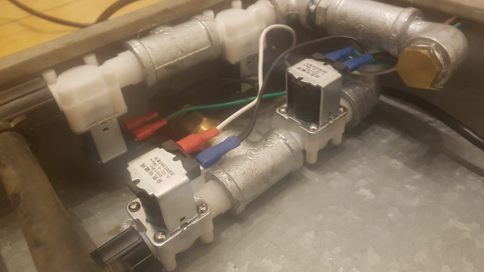
The solenoids are wired in diagonal pairs so that when one supply solenoid is open the diagonally opposite waste water solenoid is also open… this allows either outlet to become either a supply line or a waste water line… which allows you to reverse the direction of the hydraulic actuators for opening and closing the gates. Each diagonal pair are wired to one of the timer modules, one for opening and one for closing.
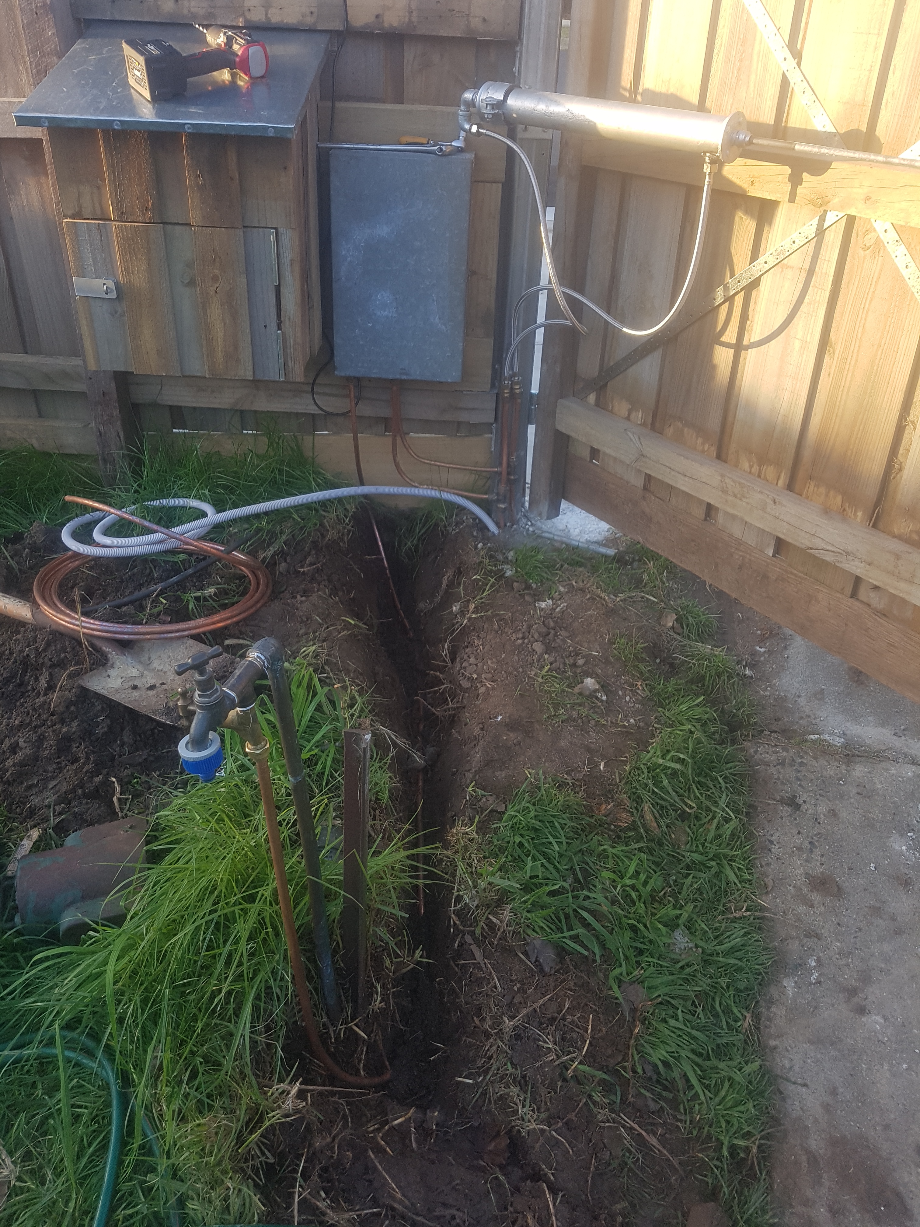
I dug a little trench and put some copper down to supply the unit from my mains water supply, I just used a copper threaded T-piece as I didn’t want to attempt flaring the original, brittle old copper pipe. It was then just a matter of making up some connecting copper pipes and running them from my underground feed pipes to the control box. You will see that the T-pieces supplying the ram directly next to the box, while also feeding the underground lines.
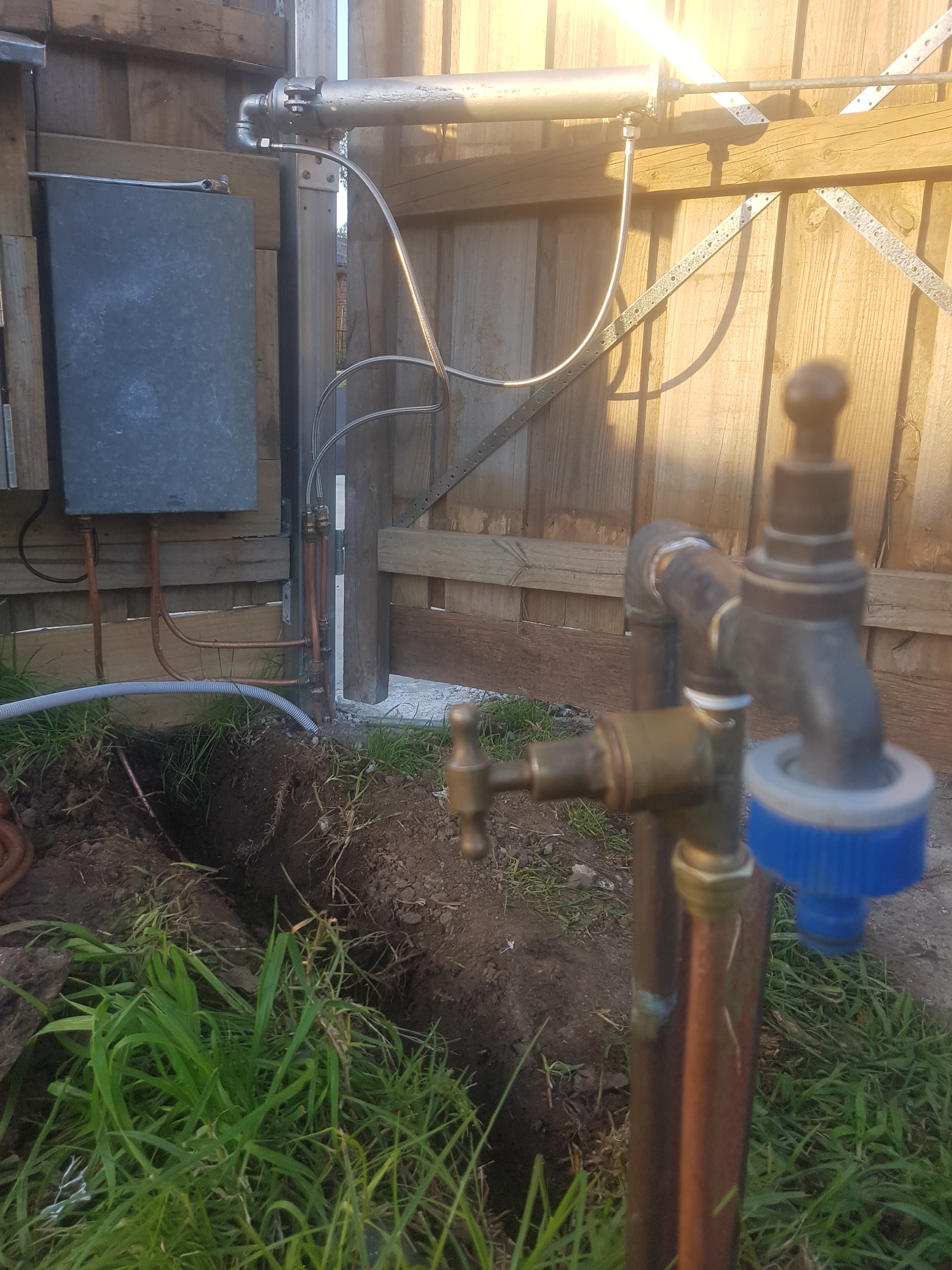
The hydraulic rams are simply connected with some standard, stainless braided PEX lines which are cheap as chips, durable and steampunk as hell.
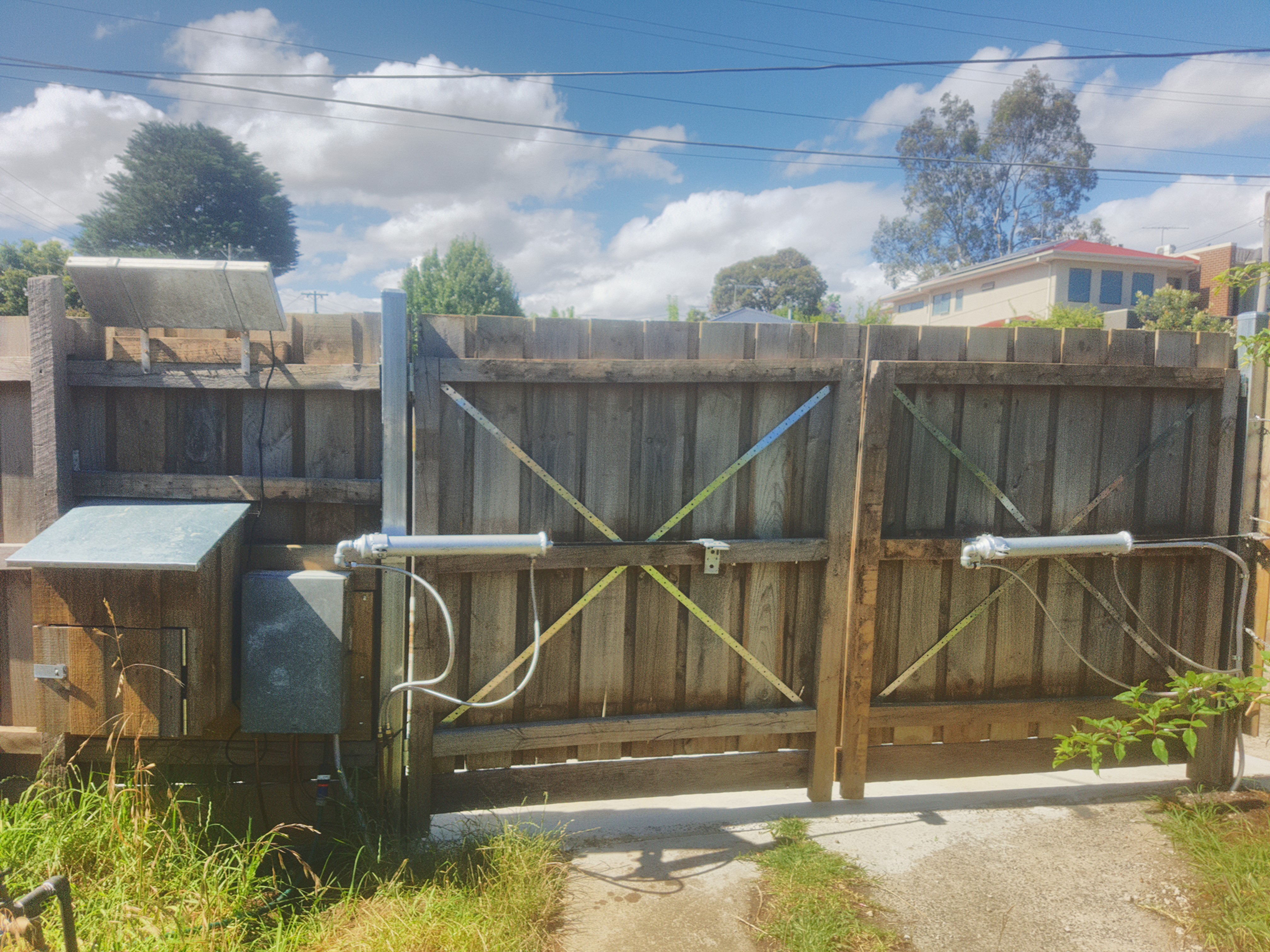
You can now see it working in all of its glory. The waster water is usually diverted onto my cherry tree through an ordinary garden hose.
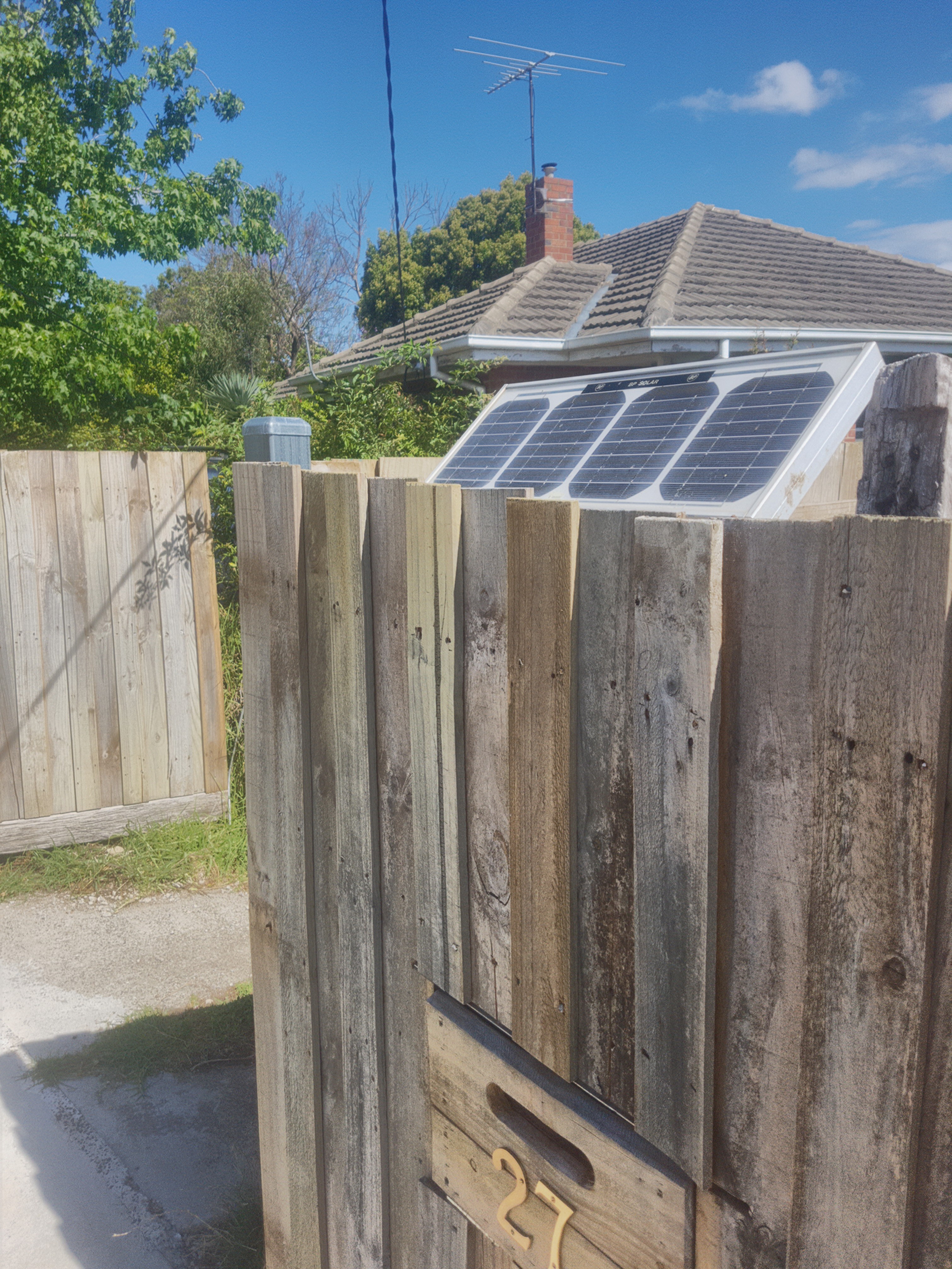
I also mounted a solar panel on the fence to trickle charge the battery, this was an old salvaged panel.
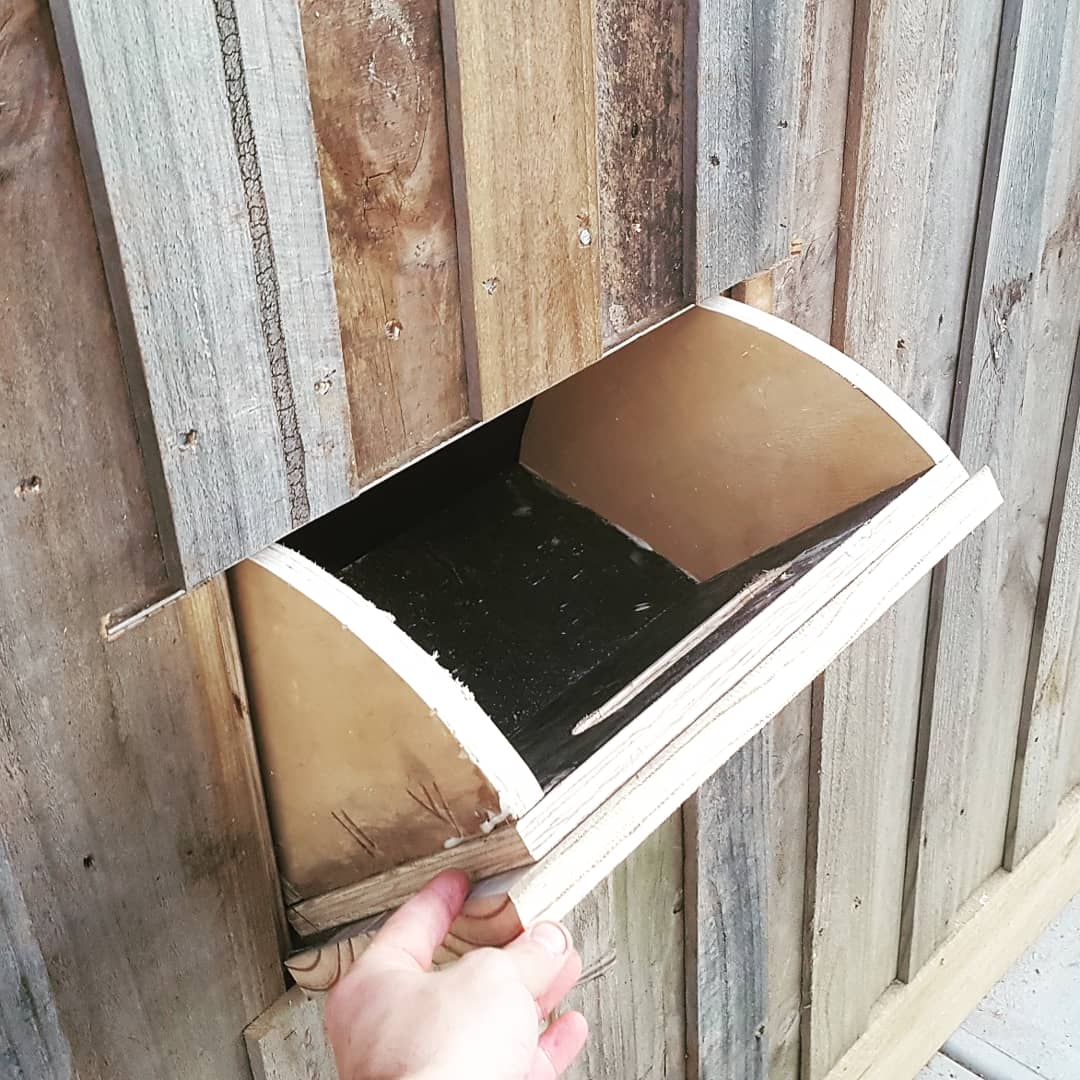
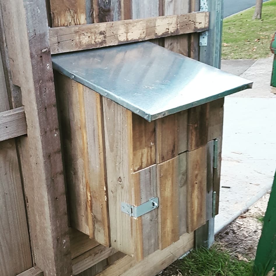
I feel at this point that I should give a little shout out to my letter/parcel box too.
Behold the steampunk.
