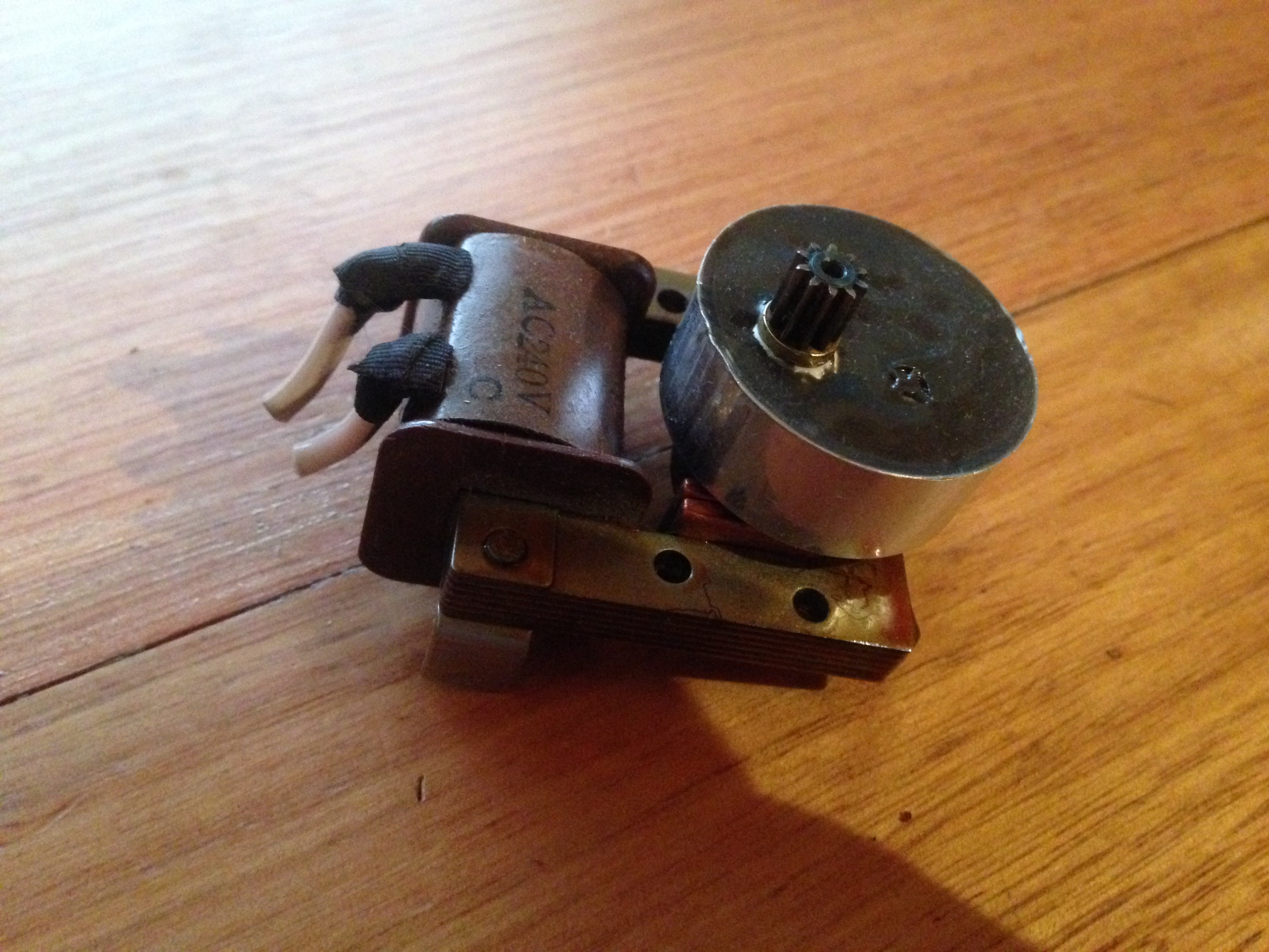
Some years ago I found what I thought was a very cool electric clock in an opp shop. It was 240 volt powered and had rotating numbers as opposed to the usual flip down numbers. Upon getting it home I realized that the mechanism had seized, after disassembling the little geared engine assembly and re-lubricating the clockwork mechanism I got quite a few years of life out of it. Sadly one day the inevitable happened and the clockwork engine stripped a tooth, unable to find a replacement motor for the clock I set about improvising a solution.
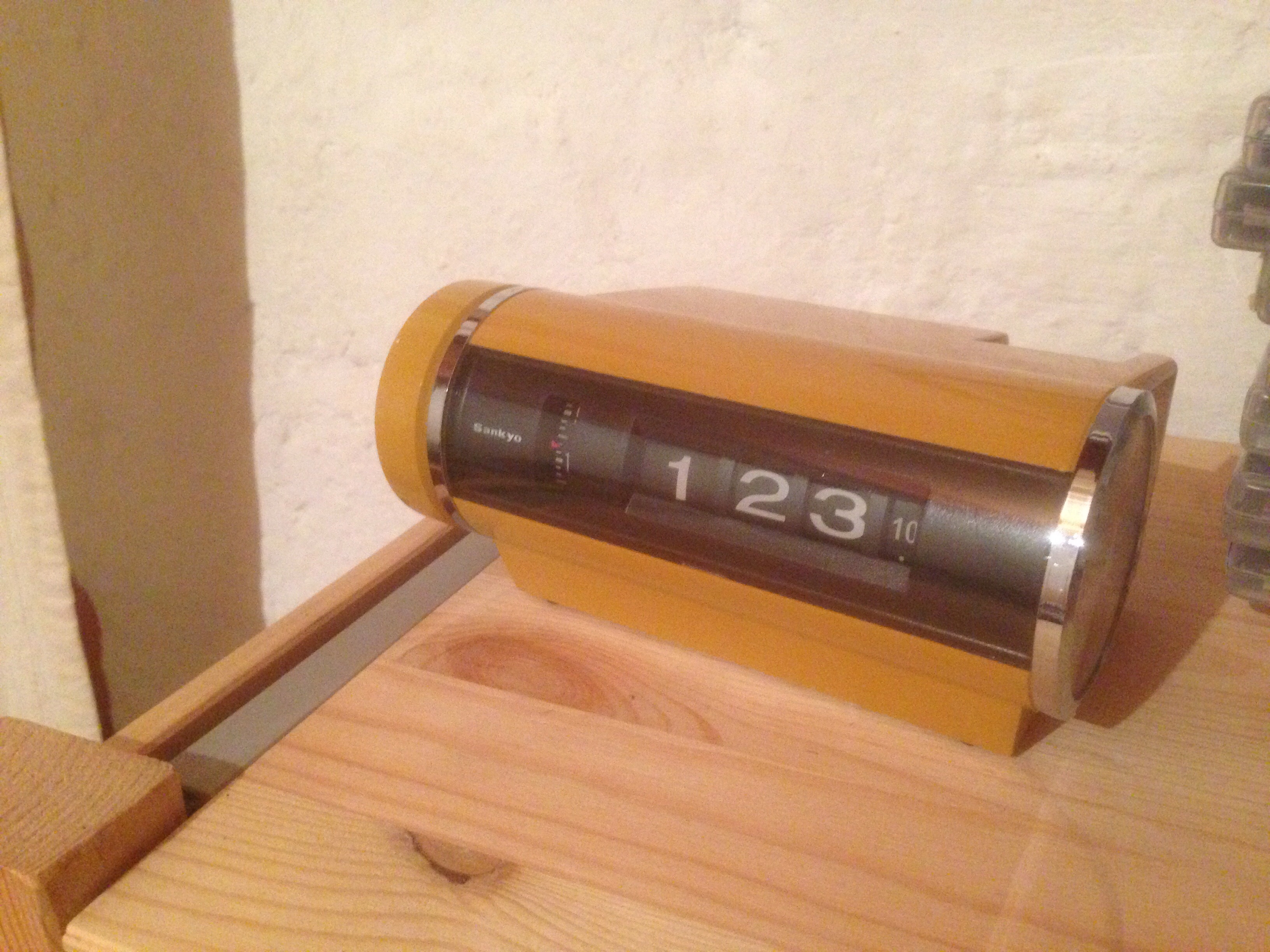
The original motor assembly relied on the 50hz oscillation from the mains power to keep time, this is very accurate way to do things as mains power is very consistent, during the time I was using the clock it never lost a minutes time.
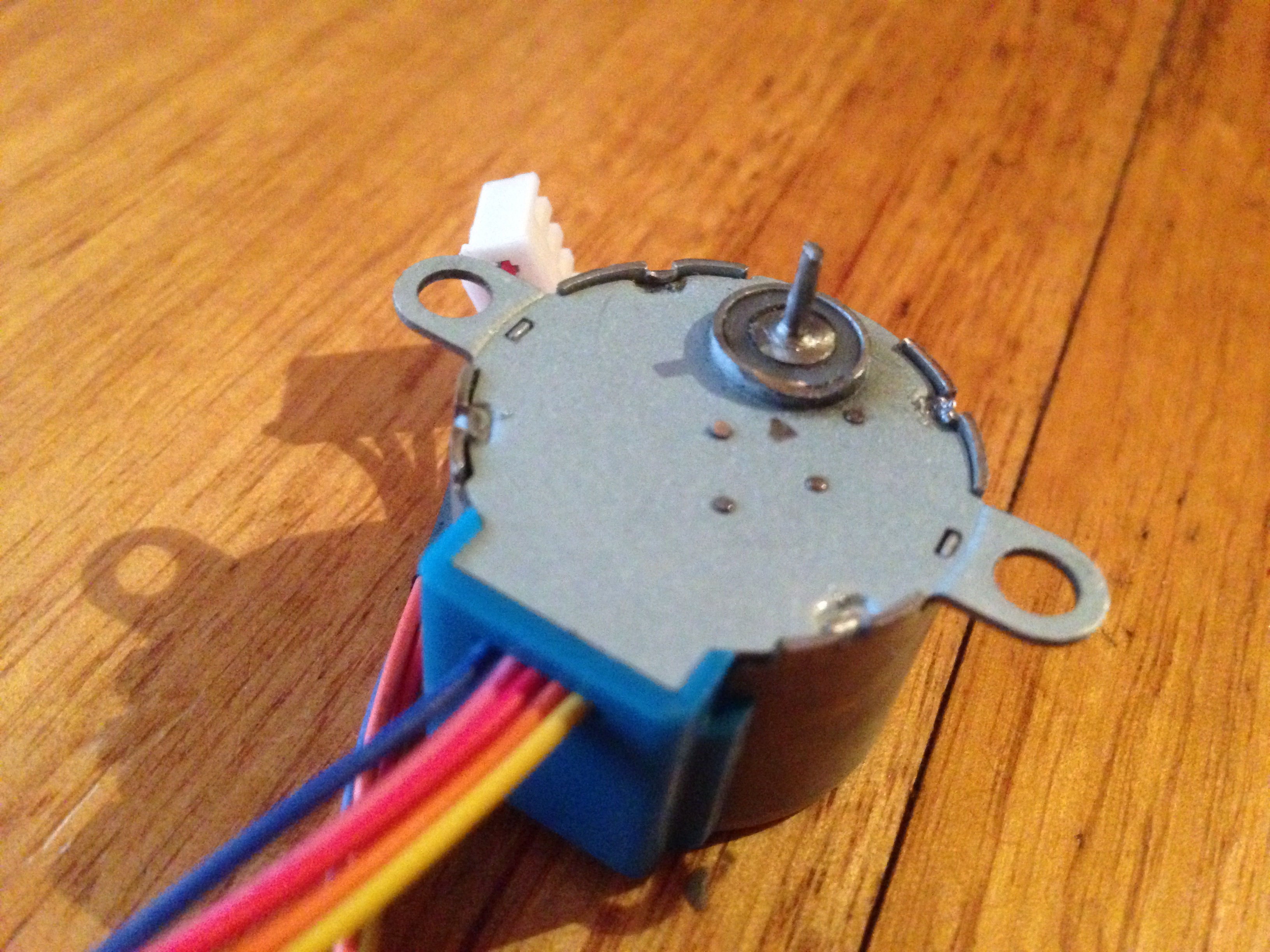
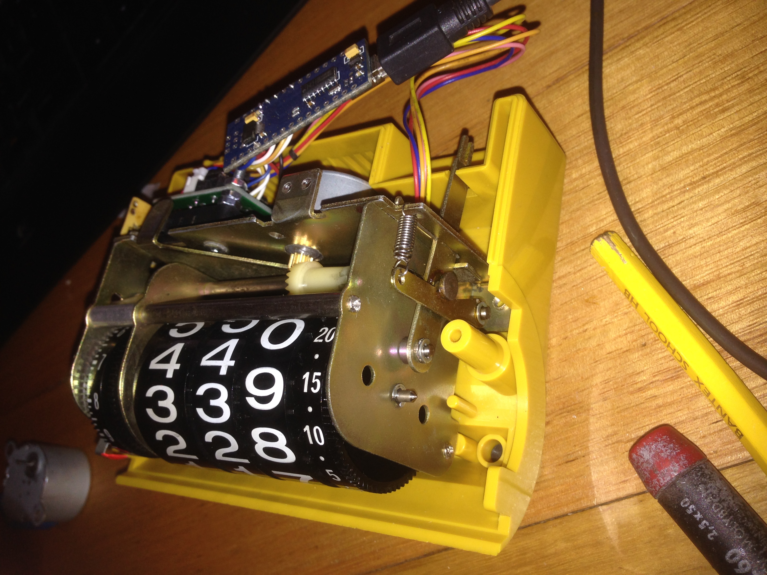
I needed a small and accurate motor that could be precisely controlled down to the 0.001 of an RPM and would fit inside the original housing. I settled on a 28BYJ-48 geared stepper motor, small stepper motor controller and an Arduino Nano. The Arduino Nano is reasonably accurate as it incorporates a crystal oscillator and can be coded to compensate for the motors unusual 283712/4455 output ratio. This can be easily done through the CustomStepper library from arduino playground http://playground.arduino.cc/Main/CustomStepper
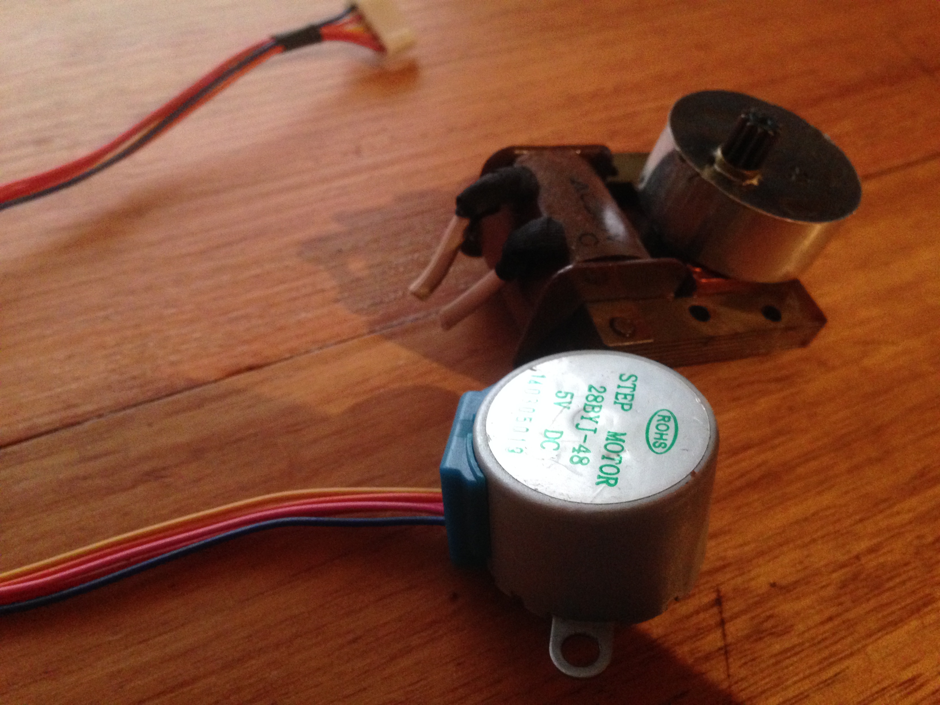
The shaft on the new stepper motor was however far too thick to fit the gear onto and needed to be machined down, I simply put the motor into the jaws of my stationary lathe while connected to the Arduino and running at 10rpm, then mounted my Dremel in the tool holder with a tungsten endmilling tool and gently machined the shaft down to fit my gear (in this case it was 1.5mm) using the rotation of the stepper motor itself to ensure that it milled true. The maximum speed of this stepper motor isn’t very high, so it was necessary to move down the shaft very slowly with the cutting tool. I found a matching 10 tooth brass slot-car gear at my local hobby shop which saved me from having to remove the gear from the original motor.
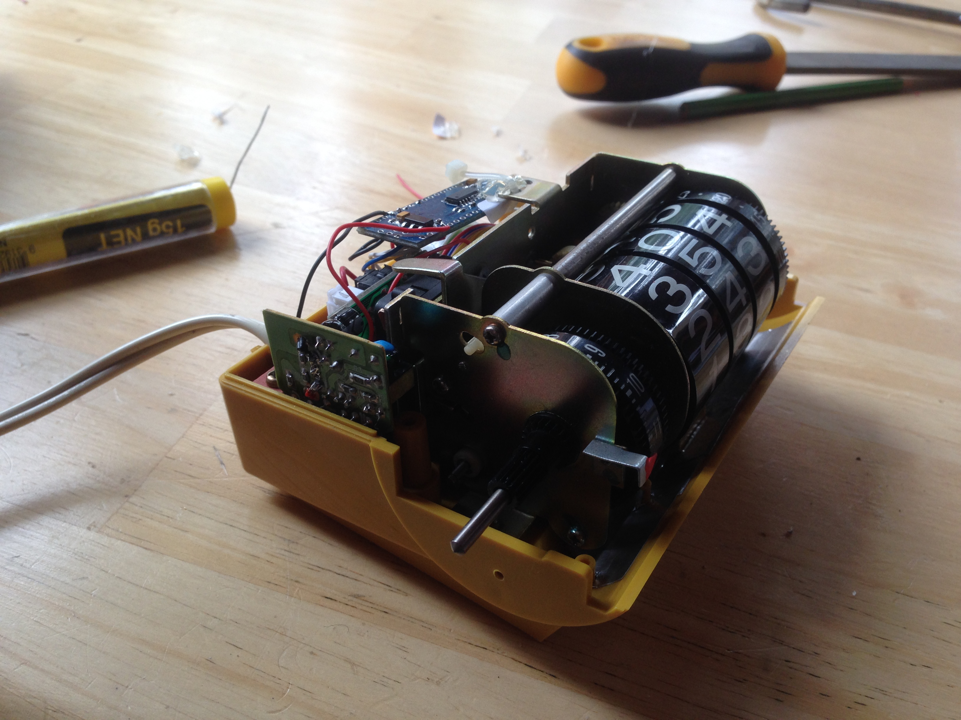
With the gear pressed on it was simply a matter of mounting all the new hardware, most of this was done with M4 bolts threaded into the back plate of the clock mechanism. The pictures should speak for themselves here.
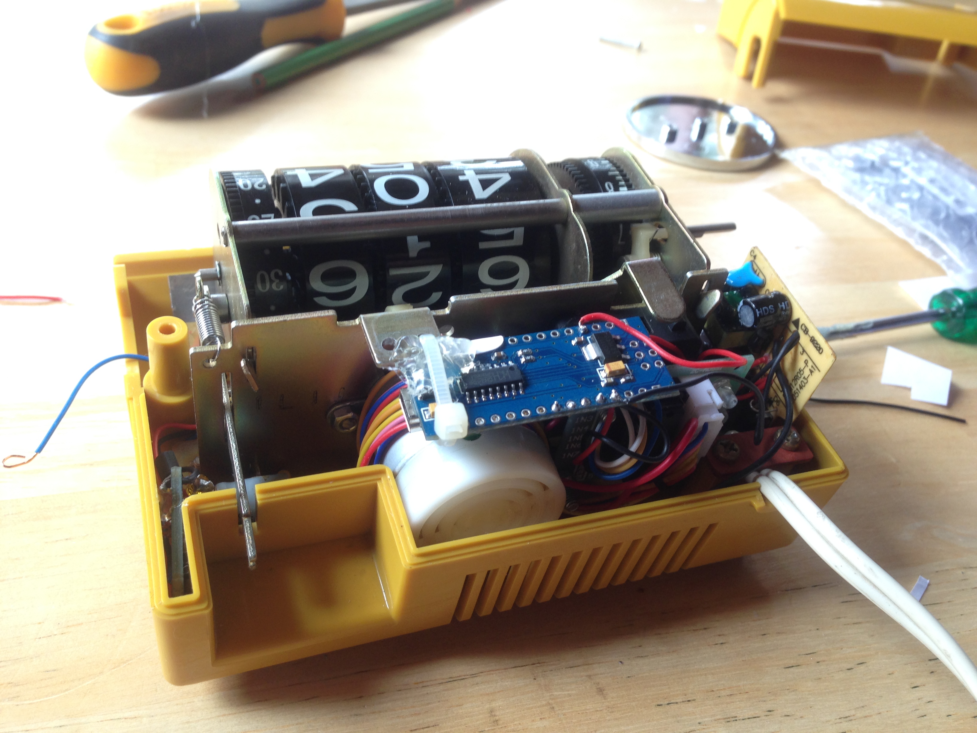
I mounted a micro switch under the original alarm actuator arm and wired this to a 5 volt piezo buzzer.
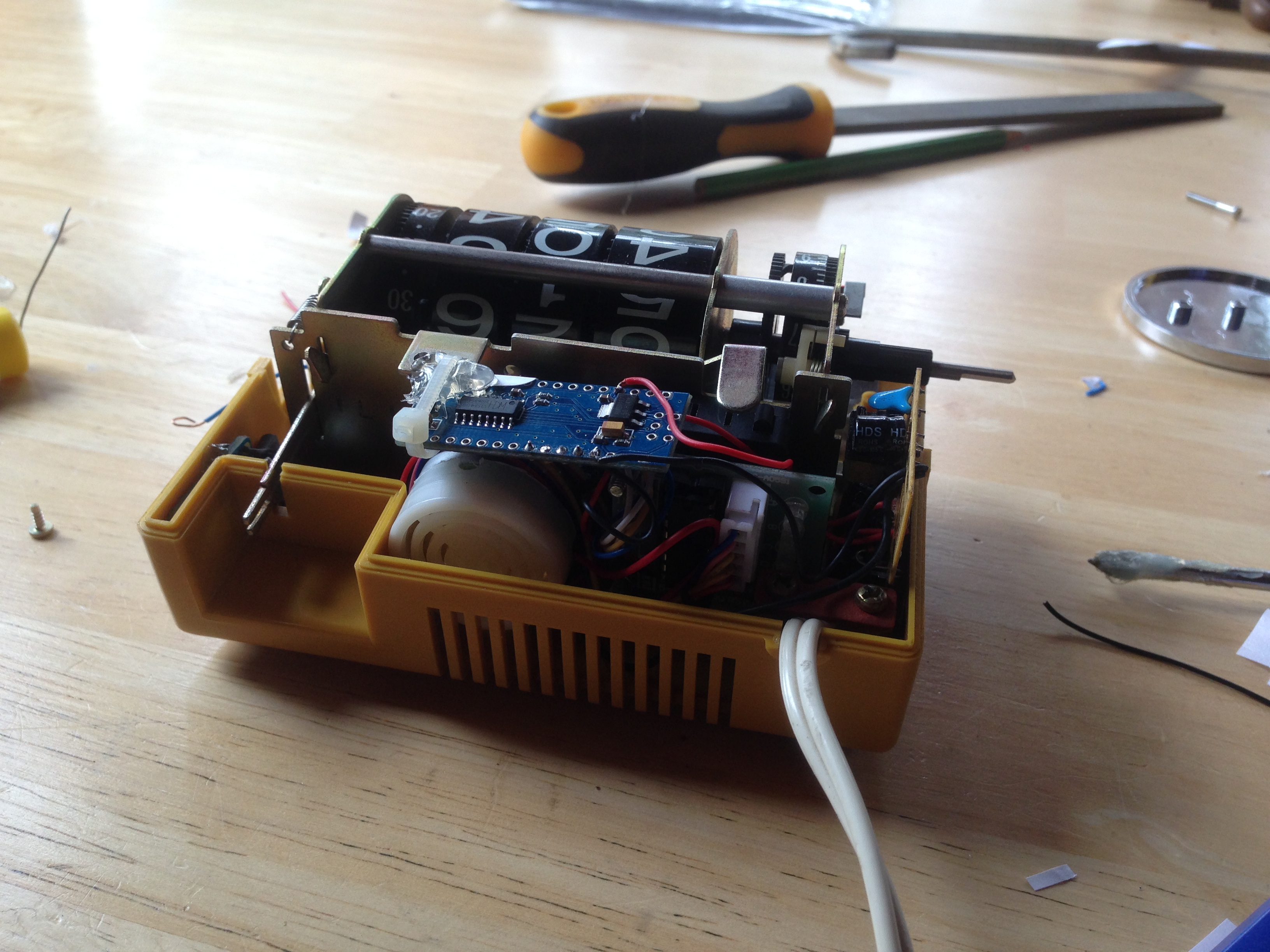
The whole thing is powered by a 5 volt power supply board which has been ratted from a USB plug-pack charger. The salvaged circuit board is mounted to the side of the housing, wedged securely into position by the top casing. I did experiment with a capacitive touch sensor switch and LED strip illumination below the numbers but the light leakage was horrendous and made the whole thing look tacky.

It keeps reasonably accurate time, losing less than a minute over a month, I have however tweaked the code to hopefully compensate for this by adding another 0.001 to the RPM value.