After playing my Sega Nomad for a little while with my modified lithium battery I started to become quite annoyed at the screen quality, in particular the edge bleeding and motion blur. I’m sure that anyone with a Nomad will sympathize with this problem. So I’ve taken the plunge and am performing a screen mod using one of the readily available 3.5 inch $20 ebay screens, however some screens are better than others, and after some experimentation I realized that some screens display an annoying AV in the top corner for a few seconds, while others do not, some screens turn off during black screens while others do not, and some screens require more voltage than the battery can provide.
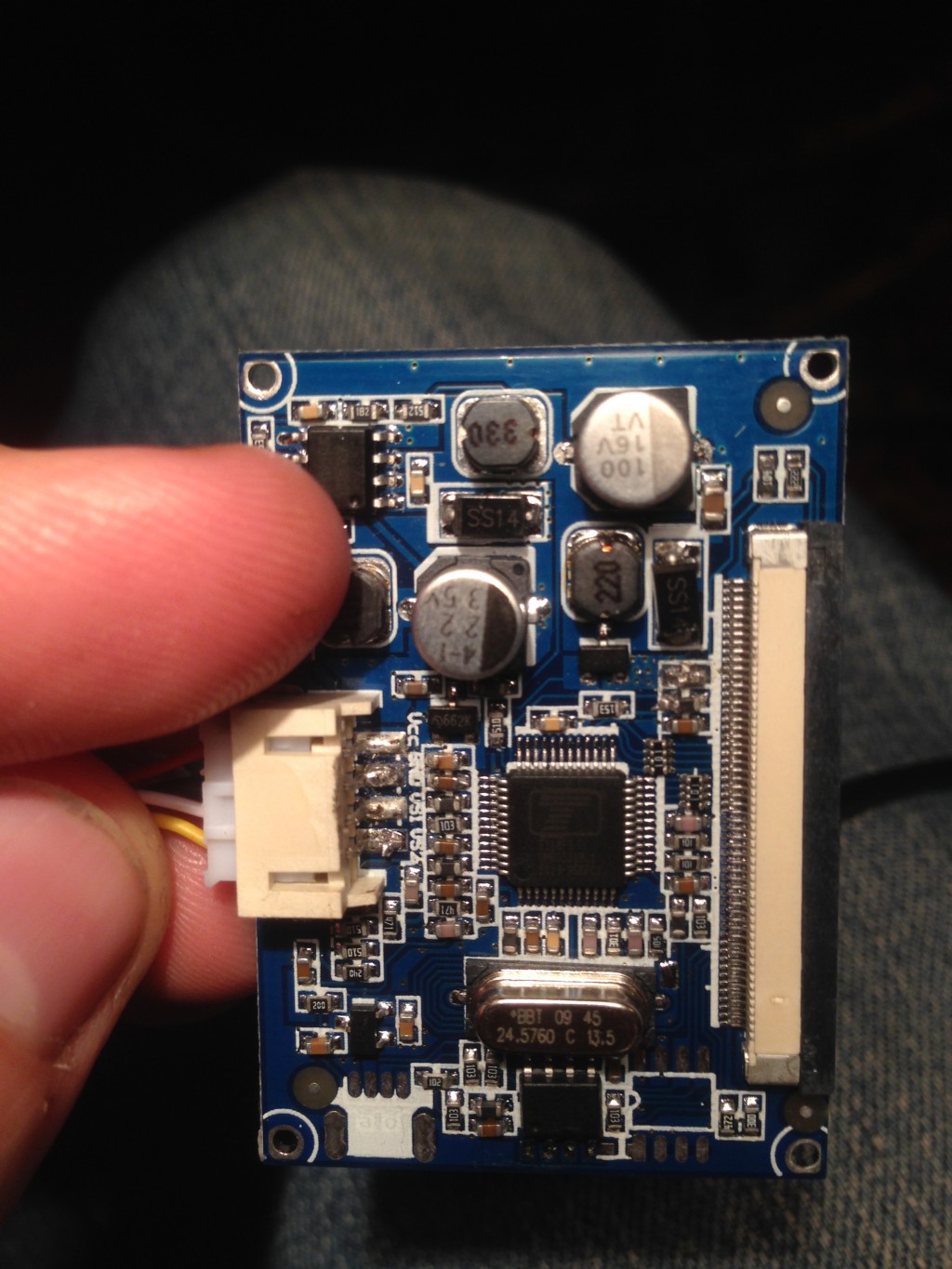
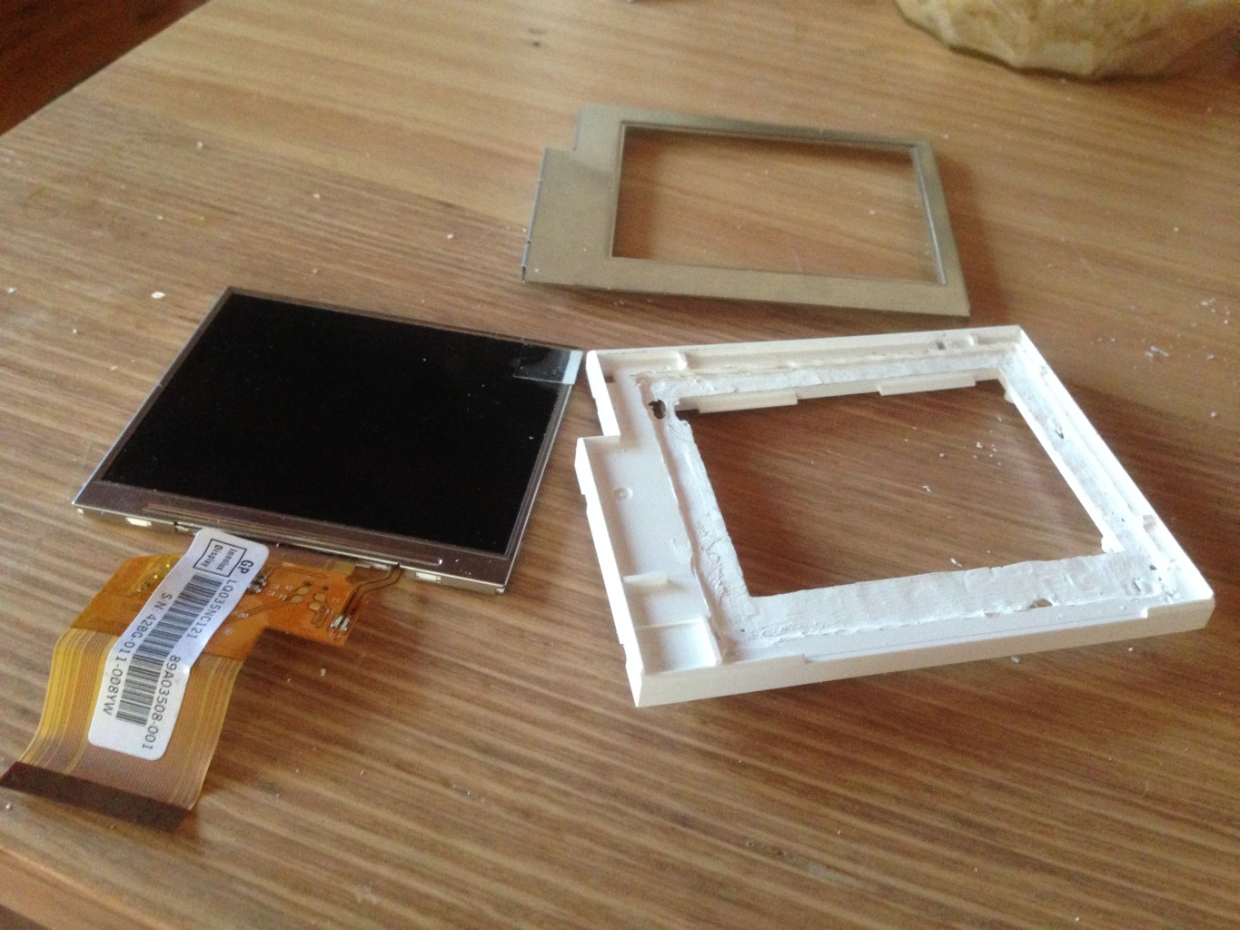
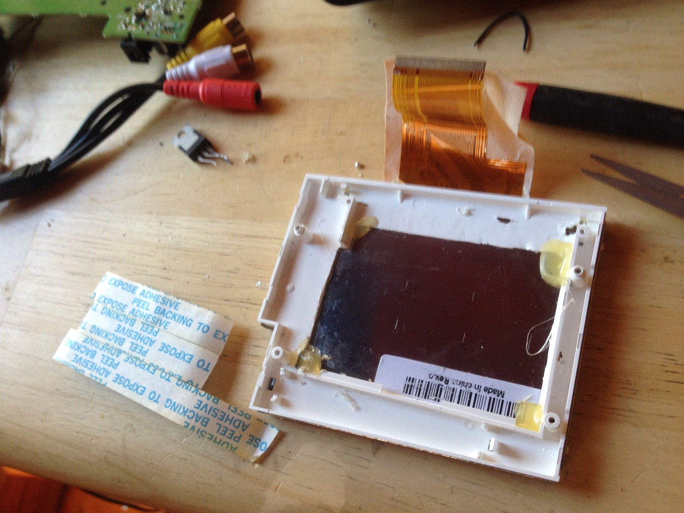
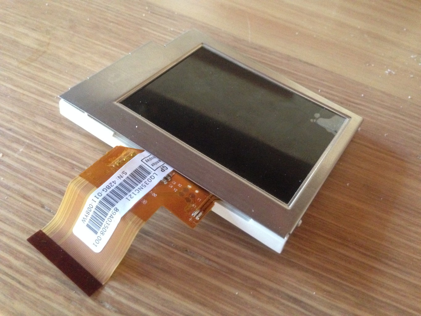
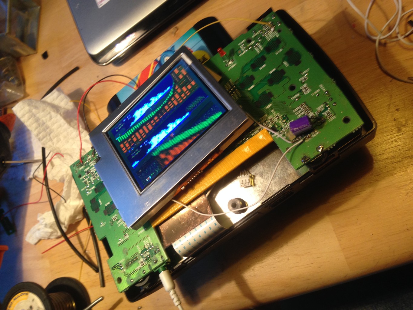
From the pictures you will be able to see the screen that I decided on, it came as only the LCD panel and driver board wrapped in polystyrene, you will be able to find this exact screen on ebay. The problem with this screen is that it likes a slightly higher voltage than the NiMh battery can provide, however with the 7.4 lithium ion battery mod there is virtually no waterfall effect over the discharge cycle, so it should keep working right up until the end (at least 5 hours by my maths). I did however bypass the shockley protection diode at the input to the screen as there is already reverse polarity protection at the nomad power socket, and shockley diodes to provide a little bit of loss.
The next problem was getting a method of controlling the brightness, I isolated the brightness control to a 3.3k resistor on the top left hand corner of the board. This is actually adjusts the level of backlighting intensity as opposed to adding or subtracting voltage to the video signal like some other screen brightness mods. When the resistor pad is earthed out, the screen becomes brighter, when disconnected the screen becomes darker. By placing a trimpot in place of this resistor it is possible to have full brightness controls. The problem is that the trimpot in the nomad is 47k and we want about 4k across the sweep…….. so i went hunting through my junk box and found a thumb-wheel style volume control trimpot from an old discman, this was a dual sweep trimpot as it used to control left and right channel volume. Each channel of this trimpot had a 10k sweep, so by running the two channels in parallel I could create my 5k sweep. You will need to ream out the two mounting points on the nomad motherboard as the trimpot is a few mm wider, and has an extra leg. The extra leg doesn’t need to go through the motherboard and can just stay horizontal above the board as it will be soldered to the pin directly beside it for support and to create our parallel resistance in the trimpot.

All you have to do is remove the 3.3k resistor at the top left of the board and solder little wires onto the pads where it once was then connect them to your new trimpot. If you look at the before and after pictures of the driver board and where I soldered my wires you’ll see exactly which resistor it is. That’s the only modification that you need to make to the screen driver board.
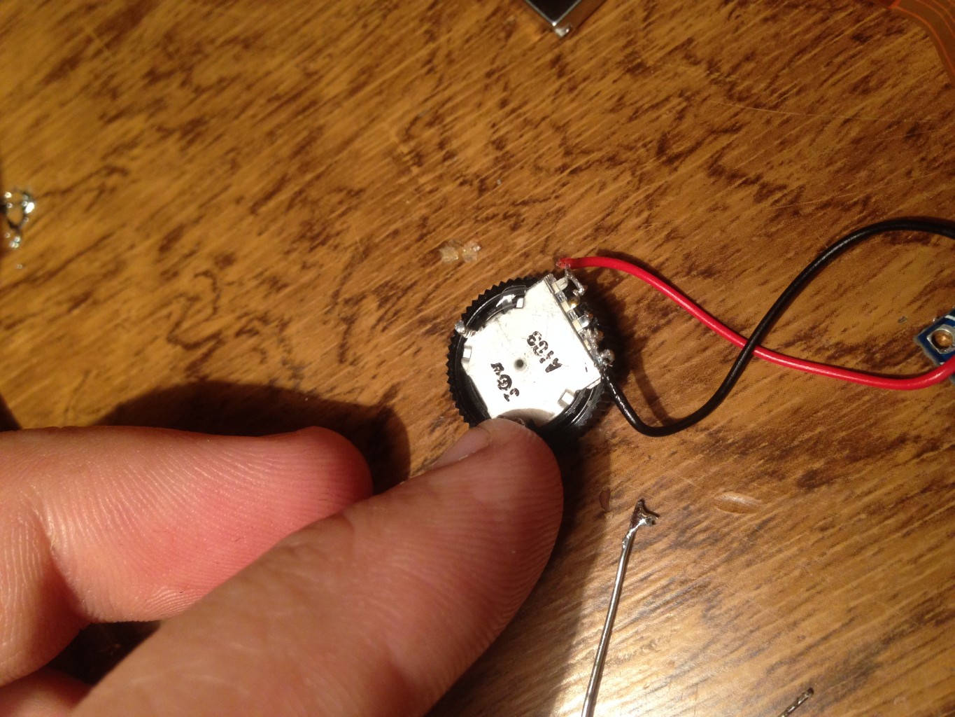
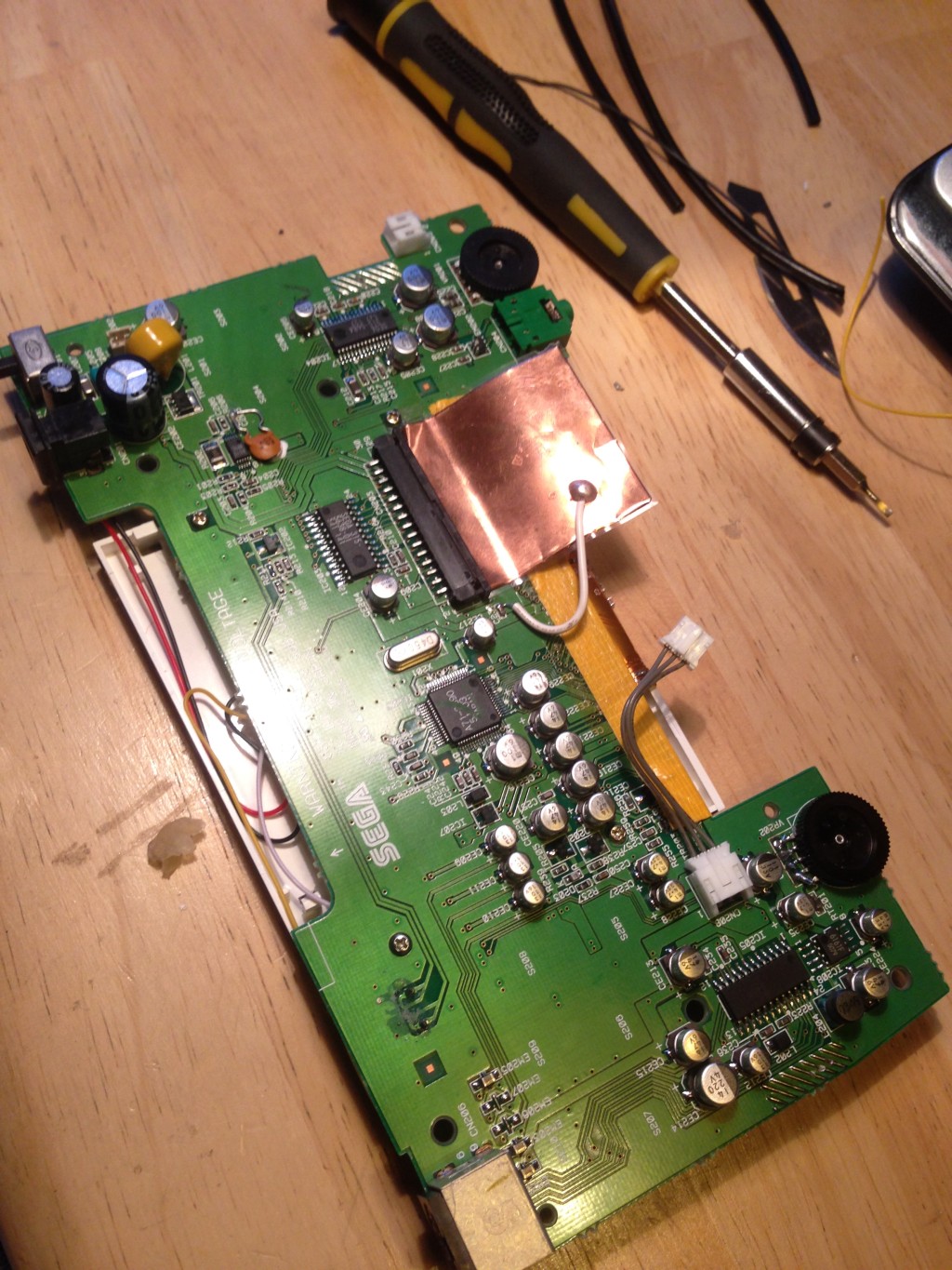
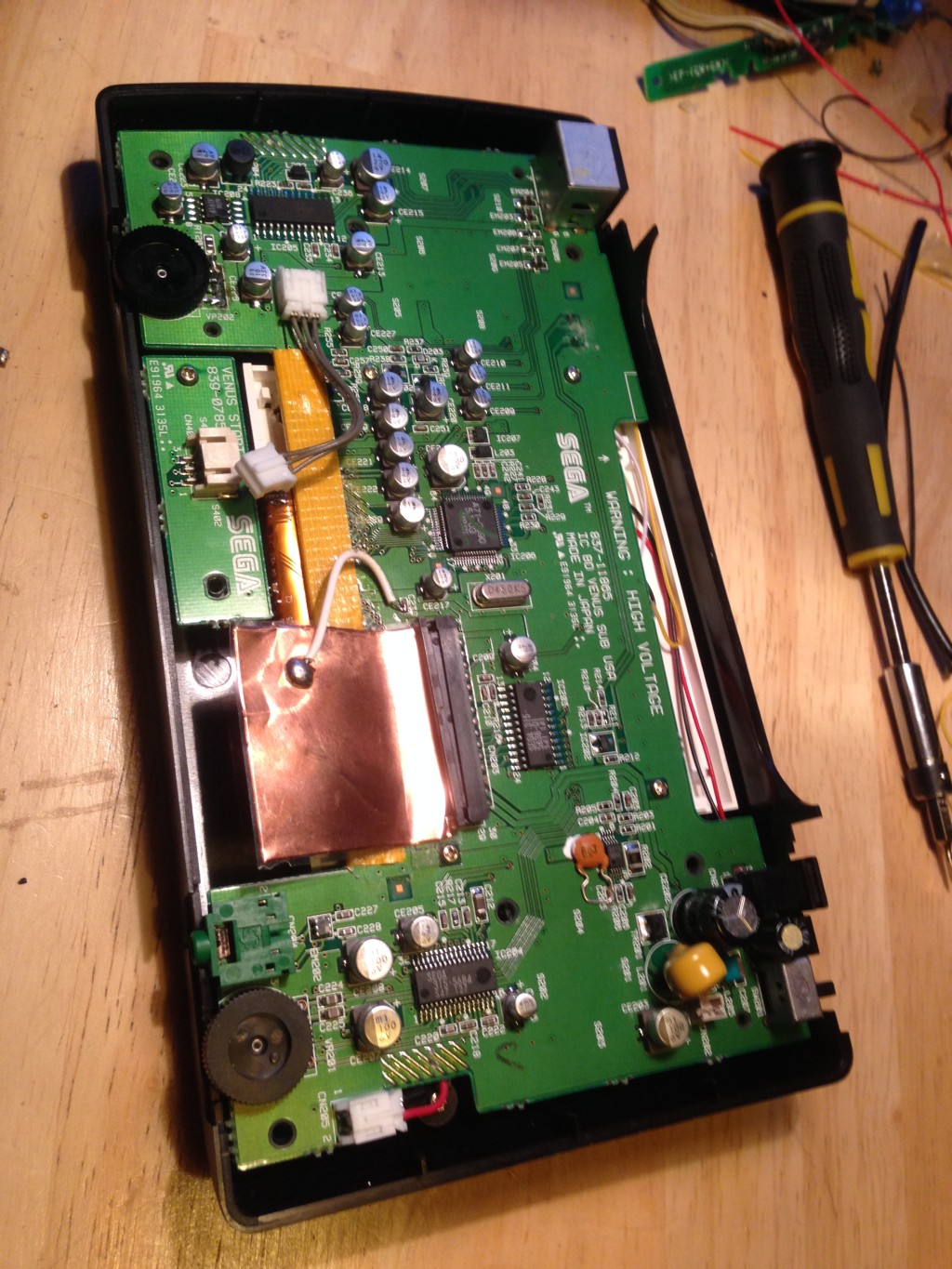
Here you can see the new trimpot mounted to the motherboard, there are a few SMD resistor that need to be removed on the reverse side in order to isolate the trimpot from the old circuitry. As for the Nomad motherboard, all I did was de-solder the old LCD screen and cover the terminals with a strip of tape to avoid shorting, I then removed the old brightness trimpot and reamed the two mounting holes at the edge of the motherboard slightly with a drill so as to fit the new slightly wider trimpot. It doesn’t matter if the body of the timpot is earthed, so you can solder it directly to the motherboard earth track in the event that you ream past the original solder pads. On the reverse side of the board under the trimpot you will see the 4 trimpot terminal holes, 2 of these holes (centre two for memory) are connected to nothing while 2 (outer two) are connected to a small SMD resistor. When you look at the board you will immediately see the two tracks running from the terminal holes to the two resistors, its very easy to spot, simply remove the resistors and your trimpot will be completely isolated from the old circuitry. Because the trimpot that I used had 5 terminals, I bridged the extra pin to its neighbour seeing as I was running the dual gangs of the pot in parallel, this can be seen in the photo. You can solder the screen brightness wires to either the top side or the bottom of the board depending on what you think looks neatest, just remember that the outer two pins on each side of the pot must be bridged in order to give you a 5k sweep.
I decided to use the old screen housing to mount my new LCD and driver board in, it required a little bit of dremelling as the new LCD was a little fatter than the old, and then a little hot glue to hold it, usually I’m not a fan of hot glue, but in this instance it was only holding it in place as the screen was already secured with the metal top plate.
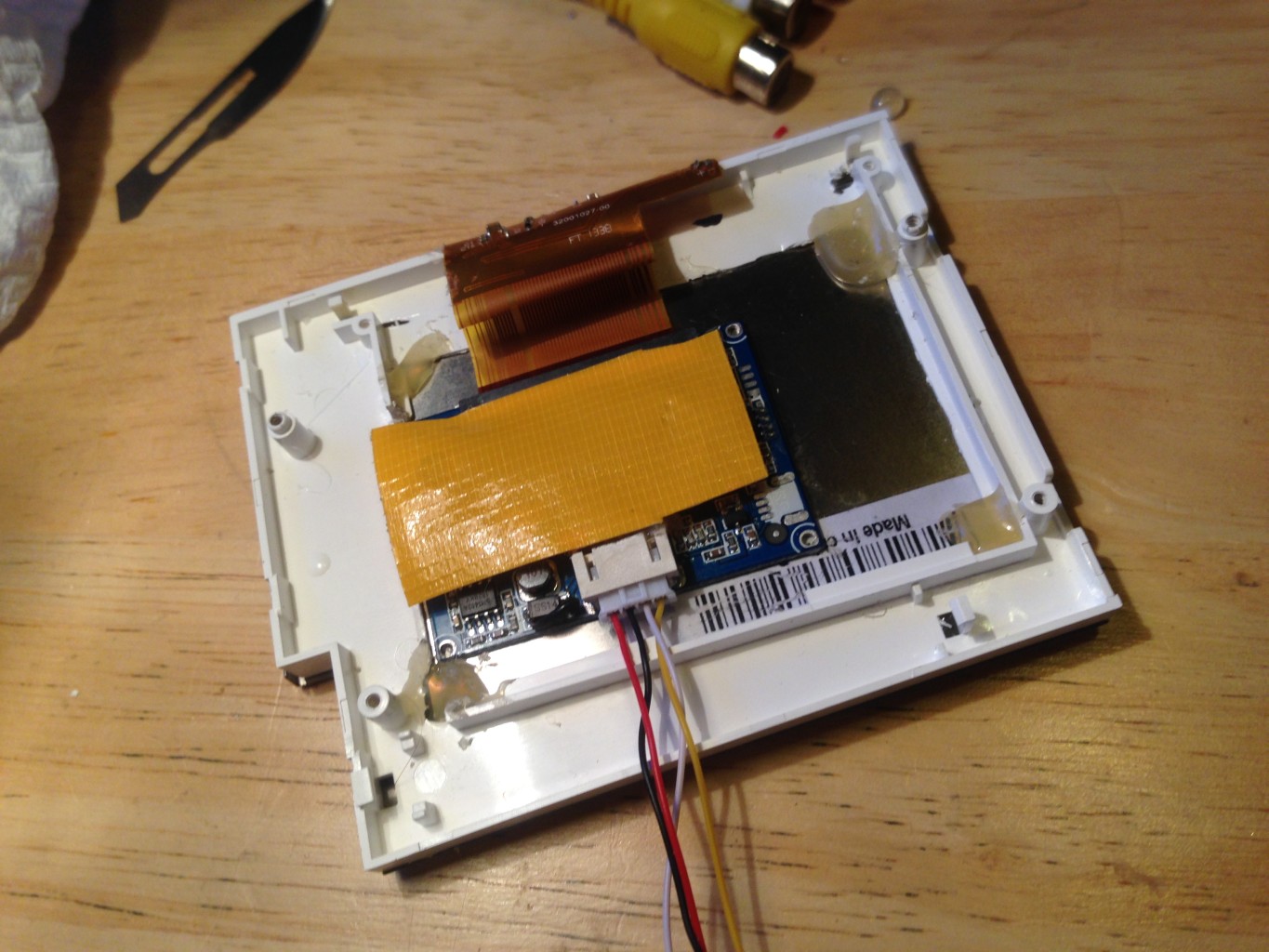
I used a little bit of cloth tape to insulate the top of the capacitors against the Nomad motherboard when it is all assembled. Note that I am yet to connect the wire for the brightness controller, I did this last as it is quite delicate and I did not want to stress my solder joints and circuit board tracks while testing.
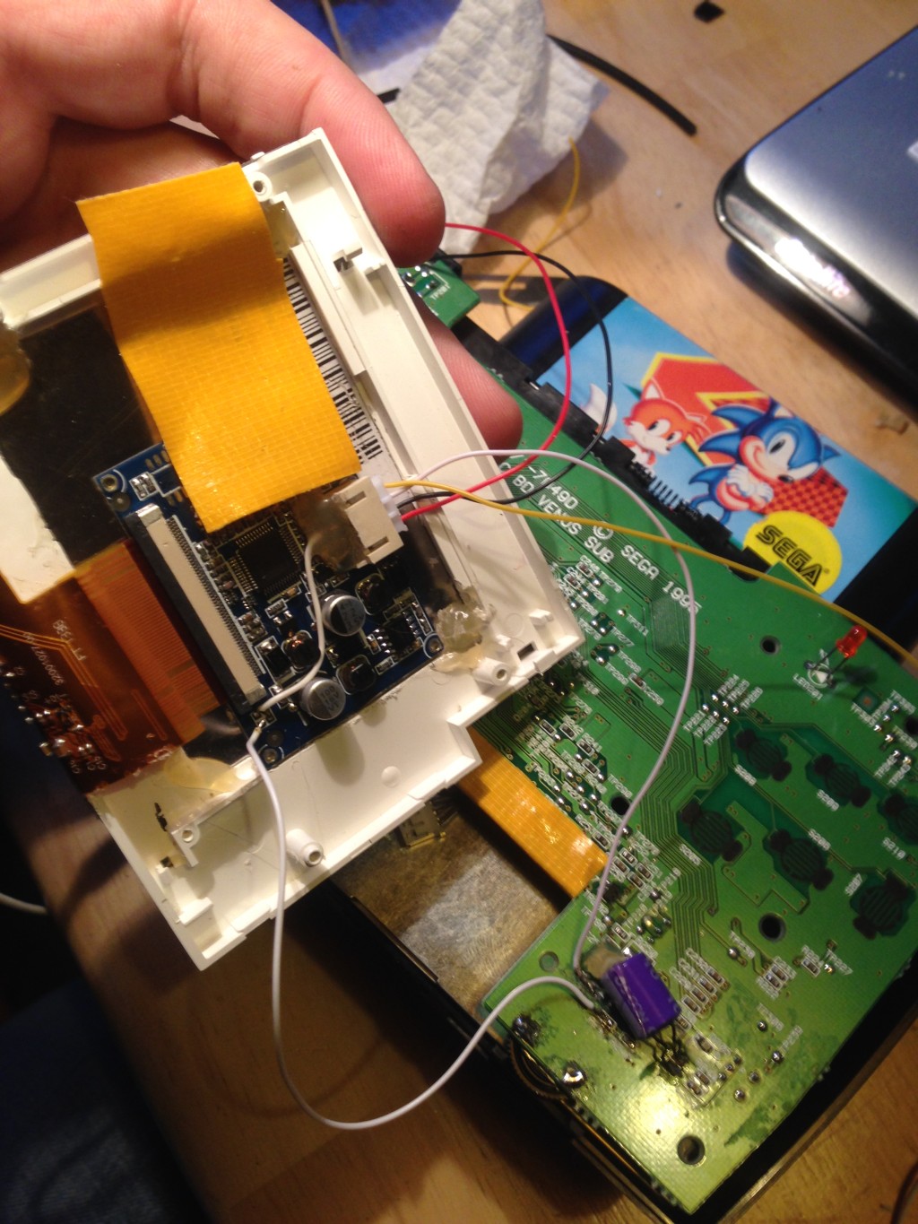
For the power connection, I simply soldered the positive wire onto the track leading to the on side of the switch (once closest to the centre/screen) and my negative terminal to the shield pin (outer pin) of the DC socket. As for the video, the pin you want when looking at the back (solder side) of the motherboard coming off the AV socket is the second from the right pin on the lower row. It’s easy to identify as it has a little unused solder pad below it. I just realised that the picture is a little blurred, but if you look at the yellow wire you can make out that it’s connected to the second pin at the right on the bottom row of the AV socket, if in doubt you can always prod your video wire on the pin that you think it is and check for signal, there are no dangerous voltages on that connector, only audio and video, so you cant hurt anything.
Now it’s just a matter of connecting up the power and video to the screen and putting it all back together
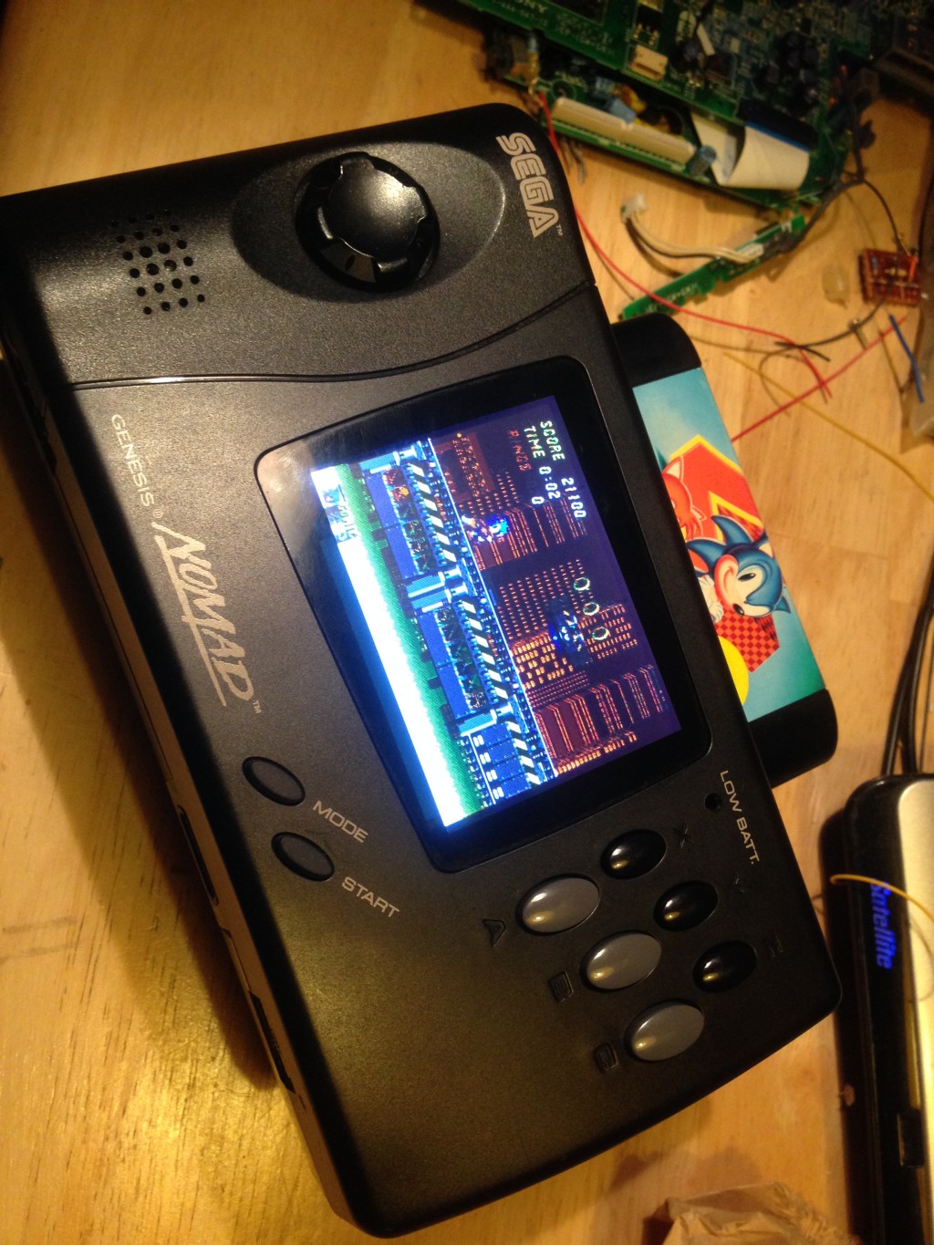
It all looks completely stock, even the brightness controller works perfectly across about 3/4 of the sweep, which is actually better than on the original nomad screen as it would wash out completely at about 2/3.


I have a question about the screen brightness control section of this article; if I’m understanding you correctly, your goal was to replace the 3.3k resistor on the LCD board with a 5k potentiometer to control brightness, correct? (You say you want both a 4k and 5k pot in the article, so I wasn’t sure)
Either way, if the built-in brightness control is a 47k pot, couldn’t you have replaced the 3.3k on the LCD board with a 5.6k, then cut the traces on the existing 47k pot (leaving it on the board), and soldered it in parallel to the new 5.6k on the LCD board? This would effectively give you a 5k pot (if I’ve done my math right):
1/((1/5.6)+(1/47)) = 5.0
You could also keep the stock control wheel exactly in place. I ask as I have just replaced the screen of my own unit, and am considering doing this mod myself.
Thanks for your time,
Mike
Additional question, you said in your article you’re replacing a 3.3kO resistor, but looking at your before and after pictures, the resistor you’ve replaced is labelled “222”, which would be a 2.2kO. If that’s the case, why do you need such a large sweep on the potentiometer? Wouldn’t this risk damaging the LCD?
You’re right, I just looked again and I was being sloppy. I doubt very much that you can hurt the circuit with a resistor that is too big, as for memory it just controls the regulator pin on the IC driving the CFL, open circuit delivering minimum brightness and closed circuit delivering maximum… it might shorten the life of the CFL tube slightly, but I doubt we would play it for long enough for that to ever happen.
For memory when I was doing it I tried the original pot with a range of parallel resistors and found the ramping to be far too sudden, but I was in a rush when I was doing it, so didn’t experiment as much as I should have. In the end I just settled on a pot that was close enough from my junk bin, but you are right, I was being very haphazard and sailing close to the wind. You could probably find a much better replacement on aliexpress.
Hey Mr. Ross, I used some of your information here on my YT video-
https://youtu.be/AZ5aytv9oIs
Thanks for putting up this information and sharing your experiences.
Great tutorial, you can still buy the screen with the brightness control resistor that I used at torbenross.com on aliexpress,
Here is the link for anyone wanting to try 🙂
https://www.aliexpress.com/store/product/3-5-TFT-LCD-Display-240×320-RGB-LCD-Display-Module-Kit-Supports-Multi-function-Display/803166_32715407296.html
Was wondering. What’s the model number of the lcd board combo? Like what’s the model number for the controller board?
This is a link to the part that I bought, I think it’s sold by a whole heap of online sellers under different names, so I would just go from a visual identification.
https://www.aliexpress.com/store/product/3-5-TFT-LCD-Display-240×320-RGB-LCD-Display-Module-Kit-Supports-Multi-function-Display/803166_32715407296.html
In my experience, even though sellers will use pictures of the old model, they actually ship the updated model without the resistor needed for brightness control. If you do actually find a seller that ships the old model, please let me know, but I’ve tried buying from a few different sellers and not had any luck.